


Master controls 11
—Owner’s Manual
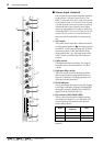
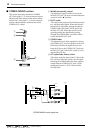
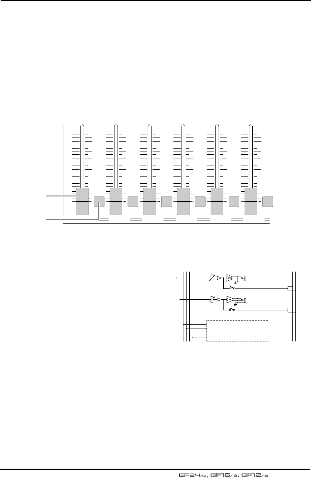
■ AUX section
This section individually controls the output sig-
nals of AUX buses 1–6. The signal that has passed
through the AUX 1–6 output channels can be
sent individually to the AUX OUT jacks 1–6
(page 17, 1 in the connector section), and can
also be sent to the PFL/AFL bus by using the AFL
switch (2 in the AUX section).
1 AUX fader
These faders adjust the output level of AUX buses
1–6. The position of the AUX faders will affect
the signals that are sent from the AUX bus to the
AUX OUT jacks and the PFL/AFL bus.
2 AFL (after-fader listen) switch
This switch sends the AUX bus signal to the PFL/
AFL bus. When the switch is on, the after-fader
signal of the AUX bus can be monitored in the C-
R OUT jacks or the PHONES jack.
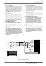
AUX section signal flow
AFL
10
5
0
5
10
15
20
30
40
AFL
10
5
0
5
10
15
20
30
40
AFL
10
5
0
5
10
15
20
30
40
AFL
10
5
0
5
10
15
20
30
40
AFL
10
5
0
5
10
15
20
30
40
AFL
10
5
0
5
10
15
20
30
40
AUX 1 AUX 2 AUX 3 AUX 4 AUX 5 AUX 6
1
2
PFL/AFL
LR
AUX
654321
AFL
Same as AUX OUT 1-2
AUX OUT 5-6:
AUX OUT 3-4:
AUX OUT 1
AFL
AUX OUT 2