


16 Front and rear panel
—Owner’s Manual
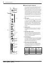
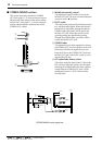
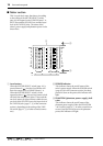
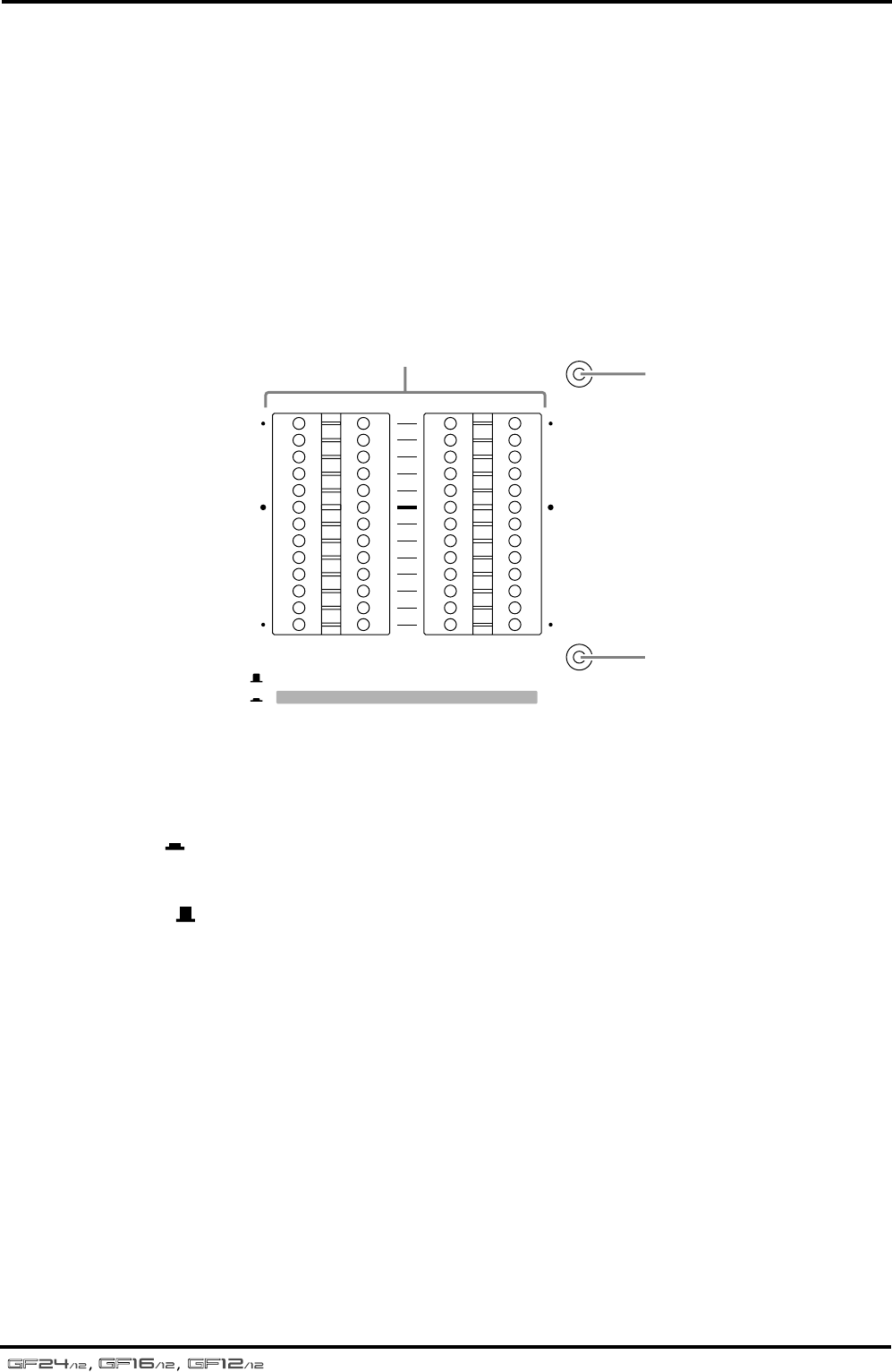
■ Meter section
This is a peak level meter that shows (according
to the setting of the METER SELECT switch,
page 14) the output levels of GROUP buses 1–4,
the ST bus, and the PFL/AFL bus, and the input
level of the TAPE IN jacks. The status of the
mixer’s power supply and phantom power is also
shown here.
1 Level meters
When the METER SELECT switch (page 14) is
pressed inward ( ), the four level meters will
show the output levels of GROUP buses 1–4.
When the METER SELECT switch is in the
upward position ( ), the two level meters at left
will show the output level of the ST bus, and the
two level meters at right will show either the out-
put level of the PFL/AFL bus or the input level of
the TAPE IN jacks (page 17, 4 of the connector
section), depending on the setting of the TAPE
IN switch (page 15, 3 of other controls/connec-
tors).
2 POWER indicator
This indicator shows the on/off status of the
mixer’s power supply. When the POWER switch
(page 20, E in the connector section) has been
pressed to turn on the power, this indicator will
light.
3 PHANTOM (phantom power supply) indi-
cator
This indicator shows the on/off status of the
phantom power supply. When the PHANTOM
+48 V switch (page 14, 1 in other controls/con-
nectors) has been slid to turn on the phantom
power, this indicator will light.
POWER
PHANTOM
LR LR
1
STEREO PFL•AFL/TAPE IN
234
PEAK
+8
+5
+3
+1
0
–1
–3
–5
–7
–10
–15
–20
PEAK
+8
+5
+3
+1
0
–1
–3
–5
–7
–10
–15
–20
1
2
3