


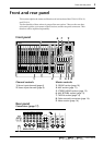

Channel controls
9
—Owner’s Manual
6
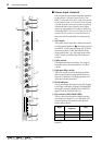
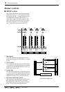
AUX controls (1–6)
These knobs adjust the level at which the input
channel signal is sent to the AUX buses 1–6. AUX
controls 1 and 2 are fixed at pre-fader, and AUX
controls 3–6 can be switched between pre/post
fader using the PRE switch (
7
). When a knob is
in the “
√
” position, the level is “nominal.”
7
PRE switches
These switches select whether the pre or post -
fader signal will be sent to AUX buses 3–6. This
setting is switched in pairs: AUX 3/4 and 5/6.
When the switch is pressed in, the pre-fader sig-
nal will be sent to the corresponding pair of AUX
buses. When the switch is in the upward position,
the post-fader signal will be sent.
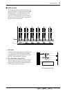
8
BAL (balance) control
This adjusts the left/right balance at which the
signal of the stereo input channel will be sent to
the ST (stereo) bus, GROUP bus 1/2, and
GROUP bus 3/4.
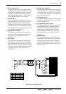
9
ON switch
This switches the input channel on/off. When
this switch is turned off, the signal of the input
channel will not be sent to the ST bus, GROUP
buses, or AUX buses. However even if this switch
is off, you can use the PFL switch (
B
) to monitor
the signal from the C-R OUT jacks or the
PHONES jack.
0
Group select switches
These switches send the signal of the input chan-
nel to GROUP buses 1–4. When the 1–2 switch is
on (pressed in) the signal will be sent to GROUP
bus 1/2. When the 3–4 switch is on, the signal will
be sent to GROUP bus 3/4.
A
ST (stereo) switch
This switch sends the signal of the input channel
to the ST bus. When this switch is on, the signal
will be sent to the ST bus.
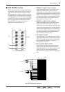
B
PFL (pre-fader listen) switch
This switch sends the pre-fader signal to the PFL/
AFL bus, allowing you to monitor it through
headphones or monitor speakers. When this
switch is on, the pre-fader signal of the input
channel can be heard from the C-R OUT jacks
and the PHONES jack, even if the ON switch
(
9
) is off.
C
Channel fader
This fader adjusts the input level of the stereo
input channel. The position of the channel fader
will affect the level of the signal that is output
from the ST bus, GROUP buses 1–4, and AUX
buses 1–6 (except when the PRE switch is on for
AUX buses 3–6).
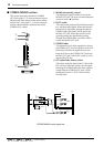
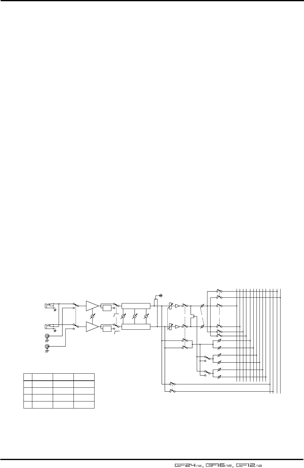
Stereo input channel signal flow
HIGH
MID
LOW
*2,*4
*1,*3
*2,*4
*1,*3
ON
ST
PFL
1-2
(MONO)
A
B
3-4
PRE
AUX 1
AUX 2
PRE
AUX 3
AUX 4
AUX 5
AUX 6
GAIN
INPUT B
80
3 Stage EQ
HPF
HA
HA
HPF
3 Stage EQ
80
INPUT A
PEAK
BAL
PFL/AFL
LR
AUX
654321
GROUP
ST
RL
4321
GF24/12
21L
22R
23L
24R
GF16/12
13L
14R
15L
16R
GF12/12
9L
10R
11L
12R
No.
*1
*2
*3
*4