


5PERCEPTION 820 TUBE
2 Description
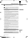
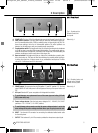
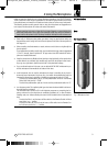
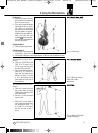
2.5.1 Front Panel
Fig. 1: Controls on the
Remote Control Unit
front panel.
Refer to fig. 1.
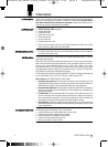
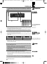
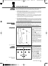
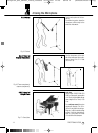
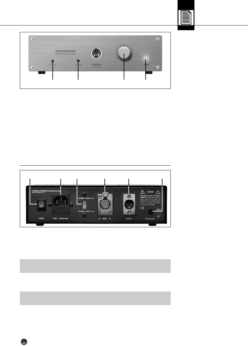
2.5.2 Rear Panel
Fig. 2: Controls, inputs, and
outputs on the Remote
Control Unit rear panel.
Refer to fig. 2.
Important!
Important!
A POWER LED:This blue LED is lit to indicate that power to the Remote Control Unit is ON.
B Polar pattern selector: This rotary switch lets you select the microphone’s polar pat-
tern from omnidirectional (fully CCW) to cardioid (center) to figure eight (fully CW). Be-
tween these settings, there are six intermediate patterns. All switch positions are
detented, so all settings are easily and unambiguously reproducible.
C Preattenuation switch:This toggle switch lets you increase the microphone’s headroom
by 20 dB for close-in recording with extremely low distortion. The preattenuation pad pre-
vents the microphone's output level, particularly at low frequencies, from overloading the
miniature transformers used in many mixer input stages, etc.
D Bass cut switch:This toggle switch lets you reduce low-end distortion caused by foot-
fall or wind noise, etc. The bass cut filter also minimizes the proximity effect that close-
in miking from less than 4 inches causes in any unidirectional microphone. The filter
rolls off at 12 dB/octave from 80 Hz downward.
E POWER switch: Turns power to the unit ON (position “I”) and OFF (position “0”). The front
panel POWER LED is lit while power is ON and goes out when you turn power to the unit
OFF.
F AC input: Standard IEC power receptacle with integrated fuse holder.
• To avoid damage, use replacement fuses of the same type and rating (125 mA/
250 V, slow-blow) only.
G Power voltage selector: Sets the input power voltage to 210 - 240 VAC (“210-240V”
position) or 110 - 120 VAC (“110-120V” position).
• To avoid damage, always make sure that the power voltage selector is set to the
same voltage as the power voltage available where you are going to use the unit.
H INPUT: 7-pin female XLR connector for connecting the dedicated audio/control cable
for the microphone.
I OUTPUT:This balanced 3-pin XLR connector provides the microphone output signal.
A
BCD
▲
!
▲
!
H I
J
G
F
E
Perception_820_Manual_final4_C030818 02/05/2009 11:26 Seite 5 (Schwarz/Black Auszug)