


7
Operating Manual -1662A Mic/Line Mixer
channel gain and/or press in the pad switch on the
rear panel. There are many gain adjustments in
the mixer itself and probably several others in
other system components which makes it possible
to overdrive an input section and then incorrectly
try to reduce the gain of the output section. The
best way to approach setting gains is to establish
the operating level of input stages first by setting
their gain as high as possible but leaving about
20dB of headroom for loud peaks, then move on to
set the master gain to produce a good meter
reading. Proceed to set the gain of equalizers,
limiters, crossovers, and amplifiers following the
mixer in the same manner, always working toward
the later stages of the system.
7.3 Excessive Noise7.3 Excessive Noise
7.3 Excessive Noise7.3 Excessive Noise
7.3 Excessive Noise
If the noise is in the form of hiss, the
problem is usually due to an input stage set for
insufficient gain and then compensating for it
by increasing the level. Try increasing gain and
reducing level. Also, check that the -20dB rear
panel pad switch is not unnecessarily enabled.
7.4 Excessive hum7.4 Excessive hum
7.4 Excessive hum7.4 Excessive hum
7.4 Excessive hum
This is usually caused by "ground loops"
in the system wiring. A complex sound system
with many sources separated by significant
distance and using several power outlets has
many opportunities for this problem to occur. If
possible, every component in the system should
be plugged into the same AC circuit with a
common ground. Use balanced input and
output connections between widely separated
components.
the use of mic inputs on channels five or six, but
only one level controls both the mic and RCA
inputs. The RCA sum inputs have a nominal
operating level of -10dBu to match most
consumer audio sources.
6.5 Outputs6.5 Outputs
6.5 Outputs6.5 Outputs
6.5 Outputs
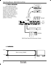
The Euroblock "A" and "B" outputs are
controlled by the output level master controls.
They are active servo-balanced with a nominal
operating level of +4dBu into any load, and are
capable of driving long lines. Outputs can be
used balanced or unbalanced. For unbalanced
output, connect the shield to
both
(-) and (G).
6.6 +48V Phantom Power Switch6.6 +48V Phantom Power Switch
6.6 +48V Phantom Power Switch6.6 +48V Phantom Power Switch
6.6 +48V Phantom Power Switch
This switch applies +48VDC to all six mic
inputs for condenser microphones. Phantom
power will not affect most dynamic mics, which
may be used along with condenser mics.
7. TROUBLESHOOTING TIPS7. TROUBLESHOOTING TIPS
7. TROUBLESHOOTING TIPS7. TROUBLESHOOTING TIPS
7. TROUBLESHOOTING TIPS
7.1 No Sound7.1 No Sound
7.1 No Sound7.1 No Sound
7.1 No Sound
Check the AC power. Is the power switch
on? Check the level meters. If they are
operating, the problem is between the mixer
and the later components in the system. If there
is no meter activity, check to see that you really
have an input signal and that it is on the desired
channel.
7.2 Distorted Sound7.2 Distorted Sound
7.2 Distorted Sound7.2 Distorted Sound
7.2 Distorted Sound
Something is being overdriven in the signal
path. If the clip indicators are active, reduce the