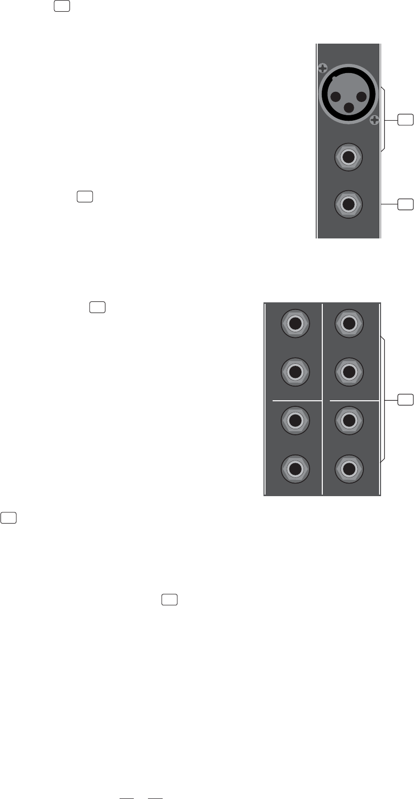
4.1 THE MIC/LINE INPUT
These are Channel 1 through Channel 4. You can connect balanced, low
impedance microphones or a low level signal to the XLR socket. On the
1/4" Line jack you can connect either a microphone or a line level instru-
ment .
Note: You shall never connect an unbalanced microphone to the XLR
socket if you do not want to damage both the microphone and the mixer.
Also, it is not possible to simultaneously use both the MIC&LINE inputs
on the same channel, use only one of them for the appropriate source on
each channel.
- PHANTOM POWER +18 Volts
It is available only on the XLR input sockets. Please make sure the power
switch is turned off before connecting a microphone to the XLR input.
4.2 MONO CHANNEL INSERT
Insert points are provided for mono MIC channels, which can allow you to
patch external signal processing devices into signal path. When you insert
a TRS jack in the insert socket, the signal will be taken out after the channel
compressor, sent to an external processor, and returned into the channel
strip immediately before the EQ section. Of course, the jacks used must be
stereo (Tip Send/Ring Return).
4.3 STEREO INPUT (CH5~CH16)
Each stereo channel comes with two unbalanced line level inputs on 1/4"
TRS jacks, which are used to connect left and right input signals. Use the
LEFT input when connect a mono input signal to the STEREO INPUT. The
last two stereo channels feature an original and exclusive double stereo
input for each stereo channel. This feature allows you to connect two stereo
sources at the same time for each stereo channel, enlarging the real
number of signals you can manage at the same time.
1
2
4.4 LOW CUT
By pushing this switch you will activate a 100Hz low frequency filter that
provides a precise cut for frequencies under 100Hz. You can use this facility
to reduce the hum noise infected by the mains power supply, or the stage
rumble while using a microphone.
4.5 THE TUBE SOUND COMPRESSOR SWITCH
The TSC switch (on the first 4 channels) activates the TUBE SOUND
COMPRESSOR and let you choose between Compressor and De-esser
functions. The two yellow LEDs show the amount of compression applied
to the input signal. Two algorithms are provided, one for soft compression
with a threshold level of 0dB, and one for hard limiting with a threshold
level of around +10dB. This dynamic processor works on the very entry
stage of the channel and it can avoid also the channel clipping, maintain
the best signal-to-noise ratio. The compression algorithm applied to the
sound is shown by two yellow LEDs.
4
5
12
3
LINE IN (UNBAL)
INSERT
MIC IN (BAL)
MIC 1MIC 1
CH5 LEFT IN (MONO)
CH9-10 IN (LEFT) CH13-14 IN (LEFT)
CH7 LEFT IN (MONO)
CH6 RIGHT IN
CH12-11 IN (RIGHT) CH16-15 IN (RIGHT)
CH8 RIGHT IN
3
1
2
3
6


