


Q-D3™ Controls and Features Cont.
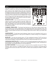
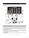
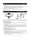
4. CHANNEL TRANSFORMER SWITCH (REPLACEABLE AND ADJUSTABLE) - These switches
are used to select the input source assigned to each channel. Each channel may only be assigned one
input source at a time. The TRANSFORMER SWITCH may be used in an up/down or left/right pattern.
To adjust the transformer orientation please follow the instructions on page 12.
5. PFL BUTTONS - These buttons are used to activate a channels “CUE” mode. A red LED next to the
PFL button will glow when a channels cue mode is activated. Cue mode will send a channels incoming
signal to the headphones. The cue level is adjusted by the Cue Level Adjustment Knob (15). Be sure
the cue level is set to minimum before putting a pair of headphones on. Be sure the Cue Mixing Knob
(14) is turned to the “CUE” position to hear the selected channel source.
6. TALKOVER BUTTON - When engaged this function will decrease all signal levels, except the micro-
phone level, by 15dB. A red LED next to the Talkover Button will glow when the talkover function is
engaged. In the OFF position all signals will remain at their normal levels.
7. MICROPHONE CONTROLS - These controls are used to adjust the microphone volume output level,
treble level, and bass levels. Turn the knobs in a clockwise direction to increase the selected value.
8. CHANNEL CUT BUTTONS - These buttons are used to cut out the Treble, Mid or Bass frequencies
of the incoming audio signal. When these buttons are depressed the selected frequency level is cut by
100%. When a Cut Button is engaged a red LED located directly above the specifi c button will begin to
glow, indicating the cut function has been activated. Depressing the Cut Button will disengage the cut
function.
9. dB METER MODE SELECTOR - This push button switch is used to change the operating mode of
the dB LED meter. When the switch is in the Master L/R (up) position, the dB meter will indicate the
master output levels. When the switch is in the PFL CH1/CH2 (down) position the dB meter will use
the left side of the meter to indicate channel one’s prefader level and use the right side of the meter to
indicate channel two’s prefader level.
10. LEVEL INDICATORS - The dual LED’s indicators are used to indicate either the master output level
or the PFL level’s of channels one and two. The level indicators will directly refl ect the operating mode
of the dB Selector Switch (9).
11. CHANNEL GAIN CONTROL - This adjustment is used to adjust an audio source signal input gain
for a channel. Never use the gain control to adjust output volume. Setting the gain level properly will
ensure a clean output signal. To properly set the gain level controls:
1. Be sure the Master Volume Control (13) is set to minimum (zero output).
2. Set the Channel Fader (3) to level 7.
3. Begin play on an audio source connected to the channel you are adjusting.
4. Be sure the LED Level Indicator Function Switch (9) is set to the PFL CH1/CH2 position.
5. Turn the PFL (5) function on, for the channel you are adjusting.
6. Use the Gain Control (11) to achieve an average output level of +4 dB.
12. MAIN POWER SWITCH - This is the main power ON/OFF button. A yellow LED above the power
switch will glow to indicating power is ON. Before main power is applied, be sure you have made all con-
nections to the mixer. Also be sure your amplifi er(s) is tuned off. Remember to avoid damaging pops,
mixer on fi rst and turned off last.
13. MASTER VOLUME CONTROL - This rotary knob is used to control the master output level
(volume). To avoid distorted output try to maintain an average output signal level +4 dB. Be sure this
volume control is always set to zero before turning the unit on.
©American Audio® - www.americandj.com - Q-D3™ Instruction Manual Page 6