


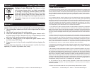
Figure 2
©American DJ® - www.americandj.com - Saturn 4™ Instruction Manual Page 5 ©American DJ® - www.americandj.com - Saturn 4™ Instruction Manual Page 6
Power Supply: Before plugging your unit in, be sure the source volt-
age in your area matches the required voltage for your American DJ®
Saturn 4.™ The American DJ® Saturn 4
™
is available in a 120v and
220v version. Due to variations in line voltage from venue to venue, be
sure to plug your “Master” unit into a wall outlet with a matching power
supply before attempting to operate.
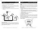
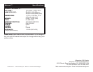
Data Cable Requirements: Your units require a standard 3-pin
XLR microphone cables for data input and data output (Figure 1).
The system includes three cables. If you require
cables of different or extended lengths, you may
uses any standard microphone cable or con-
struct your own. If you are constructing your own
cables, be sure to use standard two conductor
shielded cable (this cable may be purchased at
almost all pro sound and lighting stores). Your
cables should be made with a male and female
XLR connector on either end of the cable. Also
remember that DMX cable must be daisy chained
and can not be split.
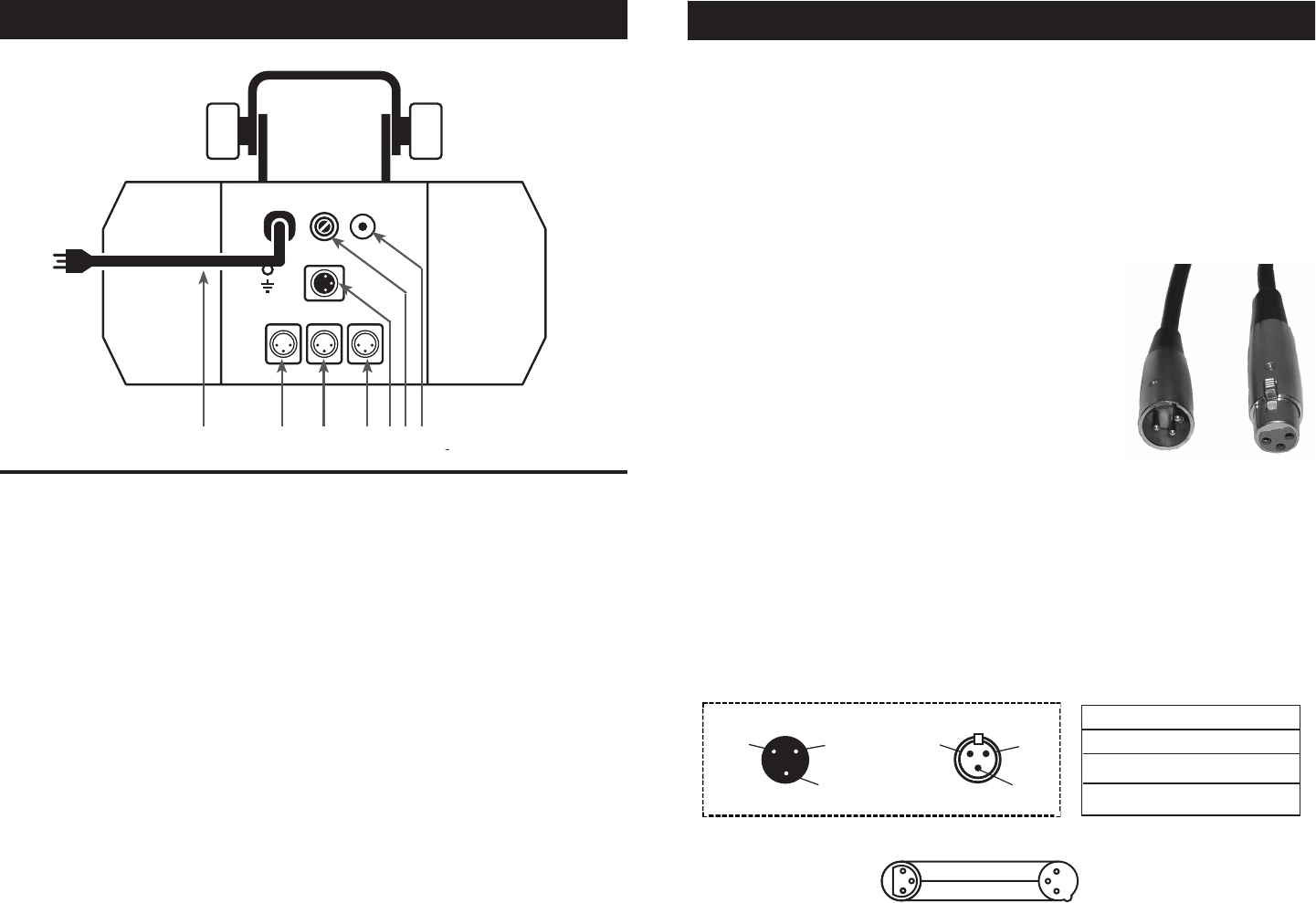
Notice: Be sure to follow gure three when making your own cables.
Do not use the ground lug on the XLR connector. Do not connect the
cableʼs shield conductor to the ground lug or allow the shield conductor
to come in contact with the XLRʼs outer casing. Grounding the shield
could cause a short circuit and erratic behavior.
Figure 1
DMX512 IN
3-PIN XLR
SOUND
REMOTE
CONTROL
INPUT
POWER
INPUT OUTPUT
SOUND
REMOTE
CONTROL
INPUT
POWER
INPUT OUTPUT
SOUND
REMOTE
CONTROL
INPUT
POWER
INPUT OUTPUT
DMX512
DMX+,DMX-,COMMON
1
2
3
Termination reduces signal errors and
avoids signal transmission problems
and interference. It is always advisable
to connect a DMX terminal, (Resistance
120 Ohm 1/4 W) between PIN 2 (DMX-)
and PIN 3 (DMX +) of the last fixture.
1
2
3
1
2
3
DMX +
DMX -
COMMON
DMX512 OUT
3-PIN XLR
Figure 3
Saturn 4™ Set Up
1 Ground
1 Ground
XLR Male Socket
XLR Pin Conguration
3 Hot
2 Cold
2 Cold
3 Hot
XLR Female Socket
Pin 3 = Data True (positive)
Pin 2 = Data Compliment (negative)
Pin 1 = Shield
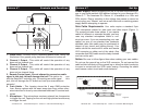
1. Power Cord - Connect only to a matching power outlet. Never use
this xture if the ground prong has been removed or broken off.
2. Channel 1 Output - This outlet will control the operation of any
slave unit as channel one.
3. Channel 2 Output - This outlet will control the operation of any
slave unit as channel two.
4. Channel 3 Output - This outlet will control the operation of any
slave unit as channel three.
5. Remote Control Input - Do not attempt to connect an audio
signal to this jack, this will damage the unit! This jack is for use
with the Saturn4/C controller only. Connecting an audio signal this
jack, this will damage the PC board and void your manufactures
warranty!
6. Fuse Holder - This housing stores the 5 amp GMA protective
fuse. Always replace with the exact same type fuse, unless other-
wise instructed to do so by an authorized American DJ service tech-
nician.
7. Microphone - This microphone receives external low frequencies
to trigger the unit. Tapping on the unit and high pitched sounds may
not trigger the unit.
Saturn 4™ Controls and Functions
654321
7