


Unpacking:
Every Sonic Beam II™ has been thoroughly tested and has been
shipped in perfect operating order. Carefully check the shipping
carton for damage that may have occurred during shipping. If
the carton appears to be damaged, carefully inspect your xture
for any damage. In the case damage has been found please
contact our toll free customer support number for further instruc-
tions.
Power Supply:
Before plugging your unit in be sure the source voltage in your
area matches the required voltage for your American DJ® Sonic
Beam II.™ The American DJ® Sonic Beam II
™
is available in a 115v
and 230v version. Because line voltage may vary from venue to
venue, you should be sure to plug your unit into a matching wall
outlet before attempting to operate you controller.
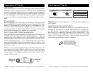
Data Cable (DMX Cable) Requirements:
Your controller and packs require a standard 3-pin XLR connector
for DMX data input and DMX data output (Figure 1). If you are
making your own cables be sure to use standard two conductor
shielded cable (This cable may be purchased at almost all pro
sound and lighting stores). Your cables should be made with a
male and female XLR connector on either end of the cable. Also
remember that DMX cable must be daisy chained and can not
be “Y”ed or split.
Notice: Do not use the ground lug on the XLR connector. Do
not connect the cable’s shield conductor to the ground lug or
allow the shield conductor to come in contact with the XLR’s
outer casing. Grounding the shield could cause a short circuit
and erratic behavior.
1
2
3
1
2
3
DMX +
DMX -
COMMON
DMX512 IN
CONNECTOR
3 PIN
DMX512 OUT
CONTROLLER
CONNECTOR
3 PIN
©American DJ Supply® - www.americandj.com - Sonic Beam II™ Instruction Manual Page 5
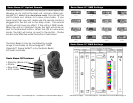
Sonic Beam II™ Set Up
Figure 2
Sonic Beam II™ Set Up
©American DJ Supply® - www.americandj.com - Sonic Beam II™ Instruction Manual Page 6
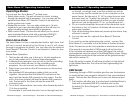
Notice: Be sure to follow gures two and three when making your
own cables.
Special Note: Line Termination.
When longer runs of cable are used, you may need to use a ter-
minator on the last unit to avoid erratic behavior. A terminator
is a 90-120 ohm 1/4 watt resistor which is connected between
pins 2 and 3 of a male XLR connector (DATA + and DATA -). This
unit is inserted in the female XLR connector of the last unit in your
daisy chain to terminate the line. Using a cable terminator will
decrease the possibilities of erratic behavior.
1
2
3
1
2
3
DMX +
DMX -
COMMON
DMX512 IN
(X-CALIBUR)
CONNECTOR
3 PIN
DMX512 OUT
CONTROLLER
CONNECTOR
3 PIN
1
2
3
Termination reduces signal errors and
avoids signal transmission problems
and interference. It is always advisable
to connect a DMX terminal, (Resistance
120 Ohm 1/4 W) between PIN 2 (DMX-)
and PIN 3 (DMX +) of the last fixture.
SOUND
REMOTE
CONTROL
INPUT
POWER
INPUT OUTPUT
SOUND
REMOTE
CONTROL
INPUT
POWER
INPUT OUTPUT
SOUND
REMOTE
CONTROL
INPUT
POWER
INPUT OUTPUT
DMX512
DMX+,DMX-,COMMON
Figure 4
1 Ground
1 Ground
XLR Male Socket
XLR Pin Conguration
3 Hot
2 Cold
2 Cold
3 Hot
XLR Female Socket
Pin 3 = Data True (positive)
Pin 2 = Data Compliment (negative)
Pin 1 = Shield