


©American DJ® - www.americandj.com - Utopia 250S™ Instruction Manual Page 10©American DJ® - www.americandj.com - Utopia 250S™ Instruction Manual Page 9
Utopia 250S™ Operation
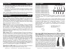
2. Follow the chart on page 14 for proper unit dip switch settings.
3. The optional Utopia/C Blackout Mini-Controller may be used with
this function for blackout.
4. After all the units settings have been set and are plugged in, adjust
the sensitivity knob on the rear of the master unit to make them
react to sound.
Note: In Stand-Alone and Master-Slave operation the units will blackout
to conserve bulb life when a sound source is not received.
Power Supply: Before plugging your unit in, be sure the source volt-
age in your area matches the required voltage for your American DJ®
Utopia 250S.™ The American DJ® Utopia 250S
™
is available in a 120v
and 220v version. Because line voltage may vary from venue to venue,
you should be sure your unit voltages matches the wall outlet voltage
before attempting to operate you fi xture.
DMX-512: DMX is short for Digital Multiplex. This is a universal
protocol used as a form of communication between intelligent fixtures
and controllers. A DMX controller sends DMX data instructions from
the controller to the fixture. DMX data is sent as serial data that
travels from fixture to fixture via the DATA “IN” and DATA “OUT” XLR
terminals located on all DMX fixtures (most controllers only have a
DATA “OUT” terminal).
DMX Linking: DMX is a language allowing all makes and models of
different manufactures to be linked together and operate from a single
controller, as long as all fi xtures and the controller are DMX compliant.
To ensure proper DMX data transmission, when using several DMX
fixtures try to use the shortest cable path possible. The order in which
fixtures are connected in a DMX line does not influence the DMX
addressing. For example; a fixture assigned a DMX address of 1 may
be placed anywhere in a DMX line, at the beginning, at the end, or
anywhere in the middle. When a fixture is assigned a DMX address of
1, the DMX controller knows to send DATA assigned to address 1 to
that unit, no matter where it is located in the DMX chain.
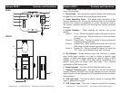
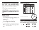
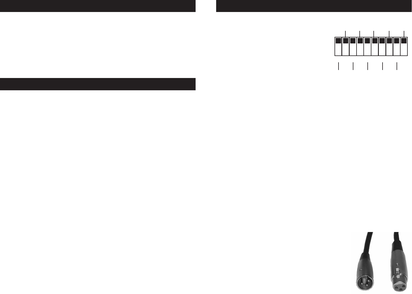
Dip-switches in DMX mode: This unit uses dip switches to assign a
DMX address. Each dip switch represents a binary value.
Utopia 250S™ Set Up
Dip Switch 1 address equals 1
Dip Switch 2 address equals 2
Dip Switch 3 address equals 4
Dip Switch 4 address equals 8
Dip Switch 5 address equals 16
Dip Switch 6 address equals 32
Dip Switch 7 address equals 64
Dip Switch 8 address equals 128
Dip Switch 9 address equals 256
Dip Switch 10 - Some unit omit dip switch 10, when a unit does
included dip switch 10 it is used for special functions such as sound
activation.
Each dip switch has a preset value. A specific DMX address is set by
combining the dip switches that sum your desired value. For example:
To achieve a DMX address of 21, combine dip switches 1, 3, and 5.
Sense dip switch 1 has a value of 1, dip switch 3 has a value of 4,
and dip switch 5 has a value of 16, the combination of the create a
DMX value of 21.
Set DMX address 21: Set DMX address 201:
Dip-switches # 1 = 1 Dip-switches # 1 = 1
3 = 4 4 = 8
5 = 16 7 = 64
= 21 8 = 128
= 201
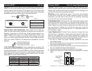
Data Cable (DMX Cable) Requirements (For DMX and Master/
Slave Operation): The Utopia 250S™ can be controlled via DMX-512
protocol. The American DJ® Utopia 250S™ is a four channel DMX unit.
The DMX address is set on the front panel of the Utopia 250S™. Your
unit and your DMX controller require a standard
3-pin XLR connector for data input and data output
(Figure 1). If you are making your own cables, be
sure to use standard two conductor shielded cable
(This cable may be purchased at almost all pro
sound and lighting stores). Your cables should be
made with a male and female XLR connector on
either end of the cable. Also remember that DMX
cable must be daisy chained and can not be split.
Utopia 250S™ Set Up
ON
198765432 10
12828 32
256651641
SP
DMX CHANNEL
Figure 1