


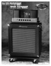
B-15R PORTAFLEX
1 2
4
3
6 7 9 10 11 12 135 8
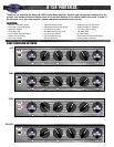
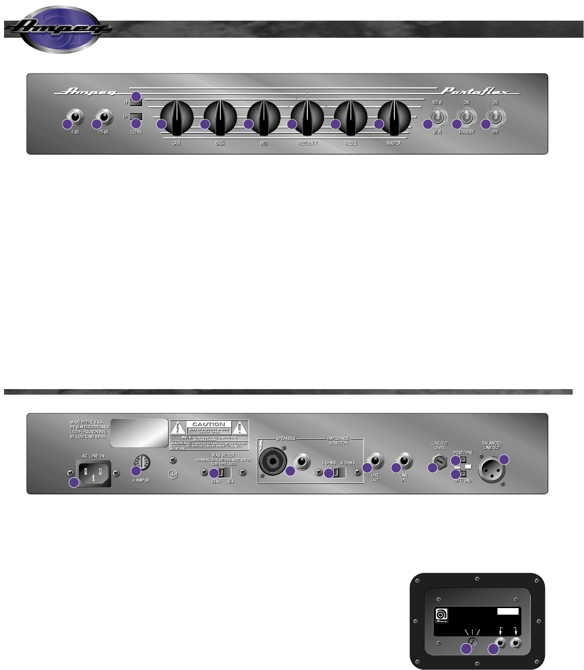
1,2: INPUT JACKS: Connect the signal cable from your
instrument to either of these jacks: if your bass has
active electronics, its output may be “hotter” than normal
– the -15dB jack is padded to accommodate such sig-
nals. If your bass has normal pickups, use the 0dB jack.
3,4: ULTRA HI / ULTRA LO BOOSTS: Engage these
pushbutton switches to boost the highs or lows as
desired. These switches activate the boosts at their “in”
positions.
5: GAIN CONTROL: Adjust this control to suit your
instrument’s signal level and your playing style – lower
output levels and softer playing styles require a higher
setting of the Gain control than high output and “hard”
playing styles. Proper adjustment of this control will give
you clean sound with the lowest noise.
6: BASS CONTROL: Adjust the low frequency output of
the amp with this control: turn the control to the left for
less; to the right for more. This control allows a range of
±25dB at 40Hz.
7: MID CONTROL: Adjust the midrange frequency out-
put of the amp with this control: turn the control to the left
for less; to the right for more. This control allows a range
of ±34dB at the selected frequency (see #8).
8: FREQUENCY: This control allows you to select one
of five midrange frequencies: 200, 400, 900, 1.5k or
2.5kHz. The setting of this control determines the effec-
tive range for the Mid control.
9. TREBLE CONTROL: Adjust the high frequency out-
put of the amp with this control: turn the control to the left
for less; to the right for more. This control allows a range
of ±30dB at 4kHz.
10: MASTER: Set the overall output level of the amplifi-
er with this control. When the Post/Pre switch (#22) is at
the IN (“Post”) position, this control also affects the level
at the Balanced Line Out jack (#24).
11: HALF-POWER SWITCH: For situations where lower
playing volumes are appropriate, flip this switch to the
“60W” (down) position. This, in effect, bypasses one-half
of the output amplification devices, producing one-half
the output power as before. Of course, when full output
is desired, flipping the switch to the “100W” (up) position
returns the amplifier to its original 100 watt state.
Note: In the 60 watt position the amplifier will deliver
approximately 40 watts into the internal speaker. To
deliver the full 60 watts into the internal 8 ohm speaker,
set the impedance switch (#18) to the 4 ohm setting.
Operation at either impedance setting is acceptable and
will yield some variances in the tonality of the unit.
Experiment with these settings to determine which
sound best suits your personal taste..
12: STANDBY SWITCH: Activate the amplifier with this
switch, after the Power switch has been turned on.
Always turn this switch off first, on last. Turn on the
Power switch (#13) at least 30 seconds before turn-
ing on the Standby switch. During breaks, turn the
Standby switch off, leaving the Power switch on. This
helps promote longer tube life.
13: POWER SWITCH: Turn on the main AC power with
this switch. Always turn this switch on first, off last.
Turn on the Standby switch (#12) at least 30 sec-
onds after turning on the Power switch.
17
MODEL:
SERIAL:
LINE: V ~ Hz
WATTS: MAX
B-15
B1500691242
120 60
14
20 21
24
22
23
15
16 18
19
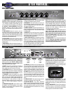
14: AC LINE IN: Use the supplied power cord to connect
the amplifier to a suitable source of A.C. voltage. This is
a grounded, three-wire cord and must be connected to a
properly grounded outlet. DO NOT attempt to defeat
the ground connection of the power cord! See the
serial number label for power ratings.
15: FUSE: This protects the amplifier from damage to
overload conditions or power line surges. If the fuse
blows, replace it only with the same size and type.
16. BIAS SELECT: Allows for instant bias adjustment
when the TYPE of output tube is changed. The setting of
this switch must match the type of tube being used! The
amplifier is shipped with 6L6 tubes installed.
17. SPEAKERS: Connect the amplifier to the internal
speaker and/or an extension speaker cabinet using these
jacks. Use heavy duty speaker cables terminated with
the proper connectors. The total speaker impedance can
not be less than 4 ohms. (Be sure to match the
Impedance Selector switch [#18] to the cabinet imped-
ance.) The B-15R’s cabinet impedance is rated at 8
ohms.
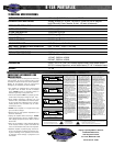
18. IMPEDANCE SELECTOR: Use this switch to match
the amplifier to the TOTAL impedance of your speaker
cabinet(s). Use the following chart to determine the total
impedance of parallel cabinets:
CABINET NUMBER OF TOTAL
IMPEDANCE CABINETS IMPEDANCE
16 ohms 2 8 ohms
16 ohms 4 4 ohms
8 ohms 2 4 ohms
19: LINE OUT: Used with the Line In jack (#20), this may
serve as an effects loop: The signal from this jack would
go to the input of the effect. Alternate uses for this jack
include providing an unbalanced line level signal for con-
necting to an external amplifier or mixing console. The
signal at this jack is affected by the Master control (#10).
20: LINE IN: Used with the Line Out jack (#19), this may
serve as an effects loop: The signal from this jack would
come from the output of the effect. Alternate uses for this
jack include providing a means to tap directly into the
internal power amplifier, bypassing the input stages com-
pletely.
21. LINE OUT LEVEL: This controls the output level of
the signal at the Balanced Line Out jack (#24).
22: POST/PRE SWITCH: This switch determines
whether or not the signal at the Balanced Line Out jack
(#24) is affected by the settings of the tone and master
level controls. With the switch at the OUT (“Post”) pos-
tion, signal is affected; with the switch IN (“Pre”), the sig-
nal is not affected.
23: LIFT/GND SWITCH: This switch lifts the ground of
the Balanced Line Out jack (#24) at the IN position.
Engage this switch only if there is excessive buzzing or
hum coming from the amplifier due to ground loops.
24: BALANCED LINE OUT: This jack provides a bal-
anced line level signal for connecting to a mixing console,
recording device or external amplifier.
25: HIGH FREQUENCY ATTENUATOR: This three
position rotary switch controls the output level of the inter-
nal high frequency driver. Use the tip of a flatblade screw-
driver to set this switch to the setting which best suits
your tastes.
26: FULL RANGE INPUTS: These are the input jacks for
the cabinet. Connect one of these jacks to the Speaker
ouput of the amplifier; the other jack may be used to carry
the amp signal to an extension cabinet if desired.
THE FRONT PANEL:
THE REAR PANEL:
25
26
SERIAL #
HIGH FREQUENCY
ATTENUATOR
FULL RANGE
INPUTS
OFF
47-267-01
–6 0
POWER HANDLING: 150 WATTS
IMPEDANCE: 8 OHMS
MADE IN THE U.S.A. BY
SLM ELECTRONICS
1400 FERGUSON AVE.
ST. LOUIS, MO 63133
B-15R