


4
The Front Panel Controls and Their Use:
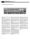
1 5 102 3 6 7 8 9 11 1312 15144
PBC228
PortaBass Amplifier
Items 1 through 10 are typical for chan-
nels 1 and 2.
1. 0dB: Connect your bass guitar here by
means of a shielded instrument cable. If
your bass has active electronics or high
output pickups, or if the Peak LED (#4) illu-
minates at low signal levels, connect your
bass to the -12dB jack (#2).
2. -12dB: Connect your bass guitar here by
means of a shielded instrument cable. If
your bass has passive electronics or low
output pickups, or if the Peak LED (#4)
does not illuminate at high signal levels,
connect your bass to the 0dB jack (#1).
3. GAIN: Use this control to adjust the level
of the signal going into the preamp. Adjust
this control until the Peak LED (#4) flashes
on strong signal peaks.
4. PEAK: This LED will illuminate when the
level of the preamp signal is close to over-
driving the amplifier. For the best signal to
noise ratio, set the Gain control (#3) so the
Peak LED flashes on strong signal spikes
during normal playing of your instrument.
5. ULTRA LOW: This switch, when de-
pressed, increases the low frequency out-
put by 6dB at 40Hz.
6. LOW: Use this control to adjust the low
frequency level of the amplifier. This control
allows an adjustment of +/-16dB at 100Hz.
7. MID: Use this control to adjust the
midrange frequency level of the amplifier.
This control allows an adjustment of +/-17dB
at the frequency selected by the Mid Freq
control (#8).
8. MID FREQ: Use this control to select the
frequency for the Mid control (#7). The Mid
Freq is sweepable from 180Hz (fully count-
er clockwise) to 1.8kHz (fully clockwise).
9. HIGH: Use this control to adjust the high
frequency level of the amplifier. This control
allows an adjustment of +/-15dB at 5kHz.
10. ULTRA HIGH: This switch, when de-
pressed, increases the high frequency out-
put by 8dB at 10kHz.
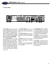
11. EFFECTS BLEND: Use this control to
adjust the level of external effects that are
connected to the Effects Send and Return
jacks (#21 and #20, rear panel). With this
control in the fully counterclockwise posi-
tion no effect is applied to the signal. As
you rotate the control clockwise the level of
the effect increases and the level of “dry”
signal decreases.
NOTE: When using the effects loop with a
compressor/limiter, this control must be
rotated fully clockwise for optimum results.
12. LIMIT: This LED illuminates when the
internal limit circuit is activated. This indi-
cates that the amplifier is nearing full out-
put and the limiter is keeping the amplifier
from clipping the output signal.
13. MASTER: Use this control to adjust the
output level of the amplifier. If the Limit LED
illuminates, reduce this control until the
Limit LED only flashes on strong signals.
14. POWER ON INDICATOR: This light
illuminates when the amplifier is turned on.
15. POWER: Use this switch to apply
power to the amplifier. The amp is on when
the top of the switch is depressed and off
when the bottom of the switch is de-
pressed.