


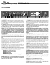
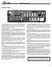

The Front Panel
0 10
10
5
4
3
2
1
9
8
7
6
0 10
10
5
4
3
2
1
9
8
7
6
0 10
10
5
4
3
2
1
9
8
7
6
0 10
10
5
4
3
2
1
9
8
7
6
0 10
10
5
4
3
2
1
9
8
7
6
Dry
Dry
Wet
Wet
32 4 5
1
Gain
Gain
Style
Style
Bass
Bass
Peak
Peak
Input
Input
Ultra Mid
Ultra Mid
Treble
Treble
Effects
Effects
Mix
Mix
Master
Master
Power
Power
Texture
Texture
0dB
0dB
-
15dB
15dB
Mute
Mute
Limit
Limit
Limit
Limit
Defeat
Defeat
Graphic
Graphic
EQ
EQ
-
12dB
12dB
+12dB
+12dB
0
8kHz
8kHz
Level
Level
5kHz
5kHz
2kHz
2kHz
900Hz
900Hz
600Hz
600Hz
300Hz
300Hz
150Hz
150Hz
80Hz
80Hz
33Hz
33Hz
Power
Power
Active
Active
1 5 7 8 9 10 14 15 16 171162 3 4 12 13 1918 20
1. 0dB INPUT: The signal output from an instrument (active or passive –
typically passive) or a line level signal may be connected here by means
of a shielded instrument cable. The signal at this jack is sent into the pre-
amp at full amplitude.
2. -15dB INPUT: The signal output from an instrument (active or passive
– typically active) or a line level signal may be connected here by means
of a shielded instrument cable. The signal at this jack is padded 15dB
before it is sent into the preamp.
3. MUTE: This switch, when depressed, mutes all outputs except the
Tuner Out (#25). A footswitch can also control muting if the Mute switch on
the front panel is left in the “out” position. (The front panel switch stays
active with a footswitch connected.) This is excellent for tuning your bass
with an electronic tuner without having to adjust any levels or turn down
your house volume.
4. TEXTURE: This switch adds a “tube emulation” stage which changes
the tone for a more aggressive sound. Using the Texture switch, you can
overdrive the amplifier without typical (and harsh-sounding) solid state clip-
ping.
5. GAIN: Use this control to adjust the level of the signal entering the pre-
amp stage. Adjust this control until the Peak LED (#6) flashes on strong
signal peaks (but is not illuminated constantly while playing). To obtain the
best signal to noise ratio, set the Gain control as described above and
adjust the Master (#14) to obtain the desired volume level.
6. PEAK LED: This LED will illuminate when the signal entering the pre-
amp stage is near the clipping level. Adjust the Gain control (#5) until a
strong signal from your instrument causes this LED to flash.
7. STYLE: Use this five-position switch to vary the tone of the amplifier.
The following table lists each of the different settings – experiment with the
Style and other EQ controls for the results which suit you best.
POSITION 1: Fully “scooped” mids (mid cut)
POSITION 2: Traditional passive tone setting
POSITION 3: Basically flat
POSITION 4: Boosted high end
POSITION 5: Basically flat with low end roll off – for loud playing with-
out “muddiness”
8. BASS: Use this control to adjust the low frequency level of the amplifi-
er. This control provides 12dB of cut or boost at 50Hz. The low frequency
output is flat at the center position.
9. ULTRA MID: Use this control to adjust the midrange frequency level of
the amplifier. This control provides 7dB of cut (fully counterclockwise) at
400Hz or boost (fully clockwise) at 800Hz. The midrange frequency output
is flat at the center position.
10. TREBLE: Use this control to adjust the high frequency level of the
amplifier. This control provides 18dB of cut or boost at 5kHz. The high fre-
quency output is flat at the center position.
11. EFFECTS MIX: This control varies the mix between the direct (dry) sig-
nal and the effects (wet) when the effects loop (#26,27) is used. Full coun-
terclockwise results in all direct signal (no effect) and full clockwise gives
all effect and no direct signal. The fully clockwise position is equivalent to
a series effects loop and should be used with such devices as limiters and
equalizers.
12. GRAPHIC EQ: This switch, when depressed, activates the graphic
equalizer. When a footswitch is used, this switch is disabled.
13. LIMIT DEFEAT: The SVT1000 employs internal limiter circuits to help
keep the power amplifier’s output clean at extreme volume levels. (All
amplifiers may begin to clip their output signals as they approach maxi-
mum output levels, resulting in potentially speaker-damaging distortion.)
These circuits may be disabled by depressing this switch. This may result
in an increase in output power, but also increases the possibility of distor-
tion. Use discretion whenever playing with the Limit circuits off.
14. MASTER: Use this control to adjust the overall output level of the
amplifier. For the lowest possible noise level, adjust the Gain control as
described in #5 and use this control to obtain the desired volume level.
15. LIMIT LED: This LED illuminates when the internal limit circuit is called
upon to keep the amplifier’s output signal clean. This indicates that the
amplifier is nearing full output and the limiter is keeping it from clipping the
output signal.
16. 9-BAND GRAPHIC EQ: Use these sliders to control the amplitude of
the frequencies indicated above each control. The center position of each
control is flat: sliding the control upward will increase the output level of that
frequency; sliding the control downward will decrease it.
17. LEVEL: Use this slider to adjust the output level of the Graphic EQ. If
the EQ’d signal is too soft, slide the Level control up; if it’s too loud, slide
the control down.
18. ACTIVE: This LED illuminates when the EQ is on.
19. POWER: This LED illuminates when the amplifier is on.
20. POWER: Use this switch to turn the amplifier on (top of the switch
depressed) and off (bottom of the switch depressed).
SVT1000 Bass Amplifier