


4
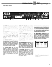
The Front Panel Controls and Their Use
V4BH Bass Amplifier
Gain Bass Midrange Frequency Treble Master Standby Power
Hi
Hi
Lo
Lo
Ultra Hi / Lo
Ultra Hi / Lo
–15dB
15dB
0dB
0dB
010
5
4
3
2
1
9
8
7
6
010
5
4
3
2
1
9
8
7
6
010
5
4
3
2
1
9
8
7
6
010
5
4
3
2
1
9
8
7
6
010
5
4
3
2
1
9
8
7
6
5
4
3
1
2
010
5
4
3
2
1
9
8
7
6
1 2 3 4 5 6 7 8 9 10 1211 13
Standby/
Standby/
Power
Power
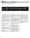
1. 0dB INPUT: The signal output from an
instrument (active or passive – typically
passive) or a line level signal may be con-
nected here by means of a shielded instru-
ment cable. The signal at this jack is sent
into the preamp at full strength.
2. -15dB INPUT:
The signal output from
an instrument (active or passive – typically
active) or a line level signal may be con-
nected here by means of a shielded instru-
ment cable. The signal at this jack is
padded 15dB before it is sent into the pre-
amp.
3. GAIN: This control adjusts the basic
level of signal in the preamp.
4. ULTRA HI: This switch boosts high
frequencies.
5. ULTRA LO: This switch, when
depressed, provides emphasis to the
low frequencies by boosting the low
frequencies and selectively cutting the
mid frequencies.
6. BASS: This is the primary low fre-
quency control. It allows for 12dB of
cut or boost at 40Hz.
7. MIDRANGE: This is the primary
midrange control. It allows for 20dB of
cut or 10dB of boost at the center fre-
quency selected by the Frequency
control (8).
8. FREQUENCY: Allows you to select
the center frequency for the Midrange
control (7), giving you a choice of five
“voices” for the Midrange. The numbers
correspond to the following center fre-
quencies as indicated: 1=220Hz,
2=450Hz, 3=800Hz, 4=1.6kHz, 5=3kHz.
9. TREBLE: This is the primary high
frequency control. It allows for 20dB of
cut or 15dB of boost at 4kHz.
10. MASTER: This controls the signal
level to the power amp and therefore the
overall listening level. It also controls the
level to the Preamp Out jack (20).
11. STANDBY/POWER LED: This is a
dual-function LED. In Standby Mode, it
glows red. In the On mode (when high
voltage is applied to the tubes) it glows
green. If it does not turn green in the
On mode, there is no high voltage
present and the unit needs servicing.
12. STANDBY: The Standby mode
allows the tubes to warm up or remain
warm without high voltage being
applied to them. This extends tube life.
This switch should be OFF when first
turning the amplifier on. Allow the unit
to warm up for 20 seconds before
switching to the ON position. During
short periods of non-use, the amp
should be put into Standby mode.
13. POWER: This supplies AC power
to the unit. Turn this switch on before
turning on the Standby switch (12), as
explained above.