


8
Operating Manual - GQX 3102, GQX 3101, and GQX 1502 Graphic Equalizer
-
+
OUT
IN
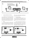
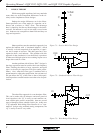
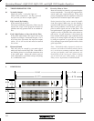
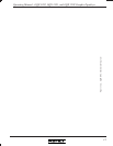
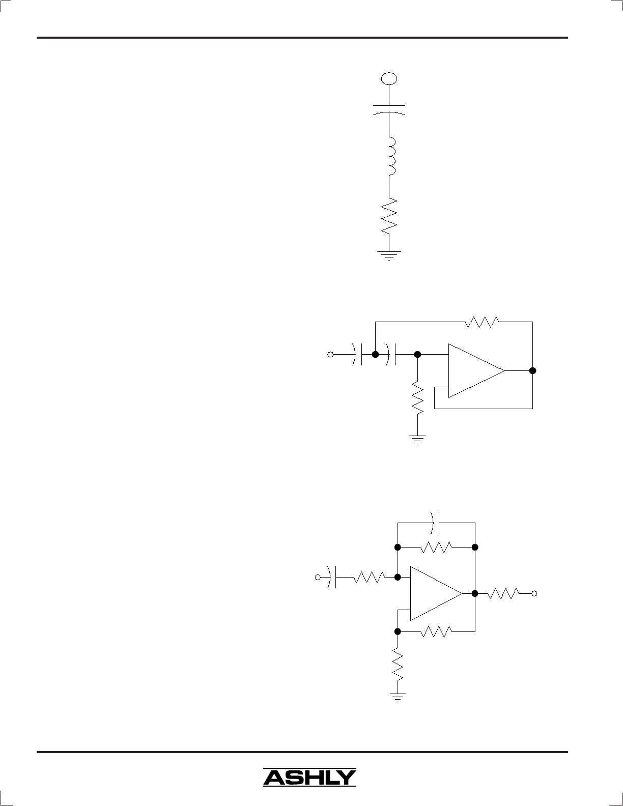
Figure 7.1: Passive RLC Filter Design
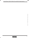
Figure 7.3: Wein-Bridge Filter Design
7. DESIGN THEORY
While most graphic equalizers look very much the
same, there are several important differences in the cir-
cuitry used to implement various designs.
Perhaps the major differences are in the filters.
Some equalizers use a filter made of a capacitor, an in-
ductor, and a resistor, or “RLC” filter. The advantage
here is simplicity, but the real disadvantage is the induc-
tor itself. An inductor is a coil of wire with a core of some
sort. Inductors are susceptible to hum fields and they are
large and expensive.
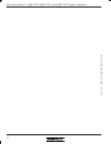
Other equalizers use the same basic approach, but
replace the inductor with a “simulated inductor”, which
is actually a circuit comprised of an amplifier, a capaci-
tor, and a couple of resistors. This adds parts but is less
expensive than a real inductor. The problem with this
approach is that simulation is less than ideal; it produces
an inductor with high resistive loss resulting in poor curve
shape when used in a filter.
Another problem with all these “RLC” designs is
that large capacitors must be used for the lower frequency
filters, limiting the choice to large, expensive non-polar
types or electrolytic capacitors with poor audio perfor-
mance. Also, when this filter type is combined with a
potentiometer to adjust the equalization, the resistance of
this pot affects the “Q” of the filter so that a little equal-
ization produces a much broader curve than a lot of equal-
ization.
The other filter approach is a true bandpass filter.
This can be made with no inductors and more practical
sized capacitors; the “Q” is easily set and remains con-
stant, and the parts count is reasonable. there are several
types of bandpass filters suitable for this job. Ashly uses
a “Q” enhanced Wein-bridge filter. Because it is a “sym-
metrical” design using matched tuning components, the
“Q” is easily set and is very stable.
Z
VAR
R
L
C
-
+
Z
VAR
Figure 7.2: Simulated Inductor Filter Design