20 series microphones
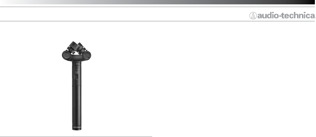
AT2022
X/Y Stereo Microphone
Features
• X/Y stereo microphone with unique pivoting electret condenser
capsules for ultimate exibility
• Provides the spatial impact and realism of a live sound eld
• Battery operation allows use with most recording devices
• Switchable low-frequency roll-off minimizes pickup of unwanted
low-frequency noise
• User-selectable 90° or 120° stereo operation for narrow or wide
pickup patterns
• Ideal for general stereo recording and eld sound capture
• Excellent channel separation
• Included fuzzy windscreen offers excellent wind protection
Description
The AT2022 is a condenser microphone designed for stereo recording.
Two unidirectional condenser capsules in an X/Y conguration pivot
to allow for 90° (narrow) or 120° (wide) stereo operation for extremely
versatile pickup. The capsules also fold at for storage and transportation.
It is designed for general stereo recording and eld sound capture.
The microphone requires a 1.5V AA battery for operation.
The microphone includes a 0.5 m (1.6’) cable terminating in a 3-pin
XLRF-type connector and a 3.5 mm (
1
/
8
”) TRS connector. The output of
the microphone is a 3-pin XLRM-type connector.
A switch permits choice of off, on/at response or on/low-roll-off
(via integral high-pass lter) to help control undesired ambient noise.
The microphone is enclosed in a rugged housing. The included AT8405a
stand clamp permits mounting on any microphone stand with
5
/
8
”-27
threads. A fuzzy windscreen, a battery and a soft protective pouch are
also included.
Operation and Maintenance
The AT2022 is designed for battery operation only; install the battery
before attempting use. WARNING: Do not attempt to use when
phantom power is present. Possible damage to the microphone
may result. (Please note, however, that the presence of a bias
voltage – from a portable recording device, for example – is acceptable
and will not harm the microphone.)
Battery installation: Unscrew the lower section of the microphone body
to reveal the battery compartment. Insert a fresh 1.5V AA battery in the
handle compartment (“+” end up), then reassemble the microphone.
Alkaline batteries are recommended for longest life. Remove the battery
during long-term storage.
Output for each stereo channel is low impedance (Lo-Z) unbalanced. The
unbalanced signals appear across Pin 2 for the left channel and Pin 3 for
the right channel. Pin 1 is ground (shield) for both channels. Output is
“Pins 2 and 3 hot” – positive acoustic pressure produces positive voltage
at Pins 2 and 3.
For correct left-right stereo orientation, position the microphone so the
word “UP” is facing the ceiling. Locating the microphone nearer the
sound source enhances the apparent width of the stereo image, while
decreasing room ambience. Moving away from the sound source will
result in a narrower stereo image and more room sound.
There are 90° and 120° indicators on the bottom side of the microphone
pivot. To select 90° (narrow) X/Y operation, rotate each element to align
the mark on the pivoting element’s base with the 90° notched indicator.
To select 120° (wide) X/Y operation, rotate each element to align the
mark on the pivoting element’s base with the 120° notched indicator.
For travel and storage, fold each element at, perpendicular to the handle.
An integral 150 Hz low-cut lter provides easy switching from a at
frequency response to a low-end roll-off. The roll-off position reduces
the pickup of low-frequency ambient noise (such as trafc, air-handling
systems, etc.), room reverberation and mechanically coupled vibrations.
To engage the low-cut lter, slide the switch toward L- CUT. For a at
frequency response, slide the switch toward FLAT.
Turn the microphone on by selecting either the L- CUT or FLAT setting.
Turn the microphone off when not in use.
Avoid leaving the microphone in the open sun or in areas where
temperatures exceed 110° F (43° C) for extended periods. Extremely
high humidity should also be avoided.


