


5
4
3
2
1
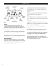
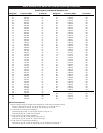
1 Shield (Ground) Shield/Bias – Shield/Audio “–“ Shield/Audio “–“
2 Bias + Out Bias + In Open Open
3 Lo-Z Mic In Mic Audio Mic Audio “+” Jumper to Pin 1
4 Source Load Jumper to Open Jumper to
(2.2 k⍀) Pin 1 Pin 1
5 Hi-Z Line In Open Open Line Audio ”+”
ATW-T101
BATT
ON OFF
ST.BY
INPUT
CHANNEL
X10 X1
5
0
9
8
7
6
3
3
2
1
Lo Hi
MIC
LVL
5
0
9
8
7
6
3
3
2
1
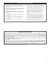
Input
Connector
Battery
Compartment
Power Switch
(Off/Standby/On)
Battery Condition
Indicator
Antenna
Channel Selector
Switches
Input
Level Control
(shown set to
“Hi”)
Fig. B
Fig. C
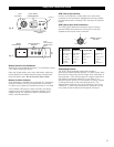
Body-pack Transmitter Setup
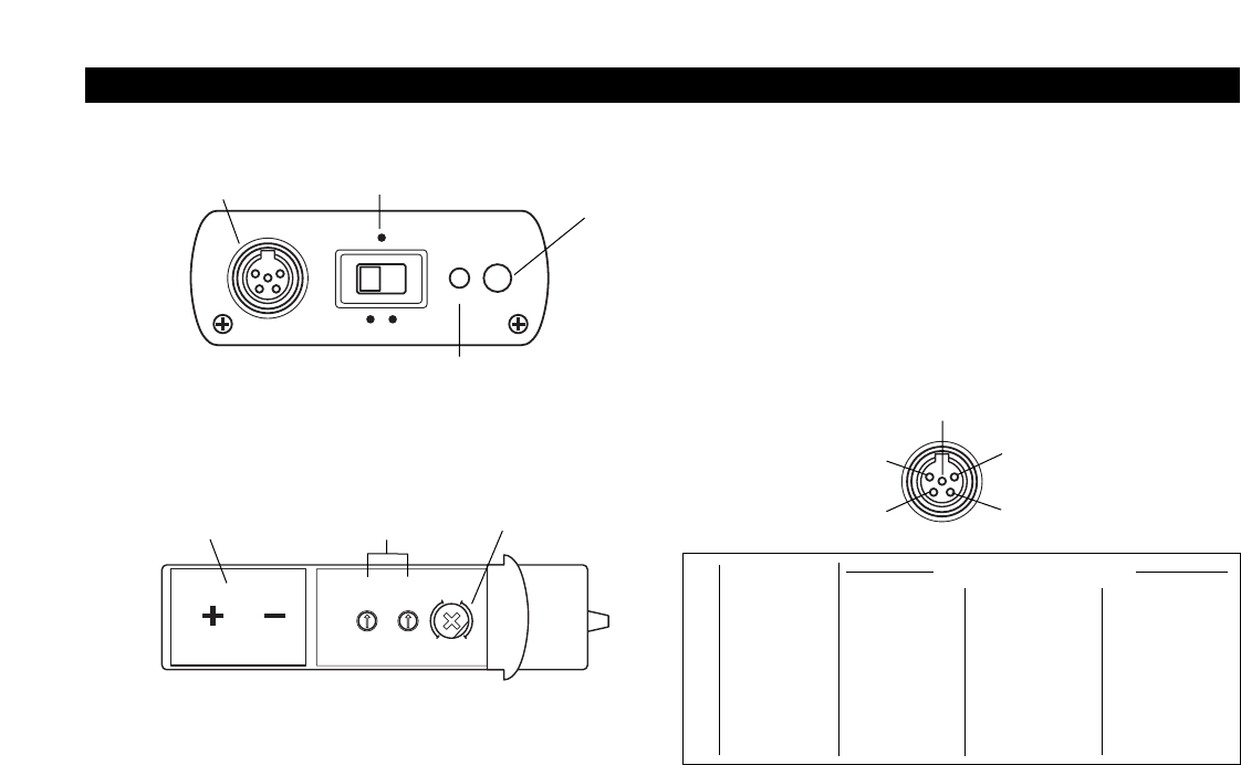
TB5M Connector,
Top View
Transmitter
InputConnections (TA5F)
Pin Connections Condenser Mic Dynamic Mic Hi-Z Line
Battery Selection and Installation
Always use a fresh alkaline 9V battery. Turn the Power switch
“Off” before inserting a battery.
Open the hinged battery door. Insert the battery, observing
correct polarity as marked inside the battery compartment.
Close the battery door.
Do not force the door closed.
Battery Condition Indicator
After the battery is installed, turn the power on. The battery
condition indicator LED (Fig. B) should flash momentarily.
If it does not, the battery is installed incorrectly or it is dead.
If the indicator LED stays on (does not flash), the battery
voltage is low and the battery should be replaced. If this
happens during use, replace the battery immediately to
ensure continued operation.
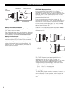
ATW-T101(x) Input Devices
Connect a microphone or audio cable to the audio input
connector on the transmitter. Microphones and input cables
pre-terminated with a matching TA5F connector are listed on
page 8.
ATW-T101(x) Input Jack Connections
The ATW-T101(x) body-pack transmitter has an industry-
standard TB5M input connector with both low- and high-
impedanceinputs plus a bias connection.
Transmitting Antenna
The ATW-T101(x) body-pack transmitter includes a
permanently-attached flexible antenna. For best results, allow
the antenna to hang freely and full length from the bottom of
the transmitter. If the received signal is marginal, experiment
with different transmitter positions on your body; or try
repositioning the receiver. Do not attempt to remove, replace
or change the length of the transmitting antenna. (The
stainless-steel mounting clip may be oriented in one of four
“directions.” Loosen its mounting screw, reposition the clip
in the case recess as desired and re-tighten the screw.)
5