


U853PM & U853PMW
Audio-Technica U.S., Inc., 1221 Commerce Drive, Stow, Ohio 44224
Audio-Technica Limited, Old Lane, Leeds LS11 8AG England
©2010 Audio-Technica U.S., Inc. audio-technica.com 0001-0157-01
In the interest of standards development, A.T.U.S. offers full
details on its test methods to other industry
professionals on request.
1 Pascal = 10 dynes/cm
2
= 10 microbars = 94 dB SPL
1
Typical, A-weighted, using Audio Precision System One.
Specications are subject to change without notice.
Specications
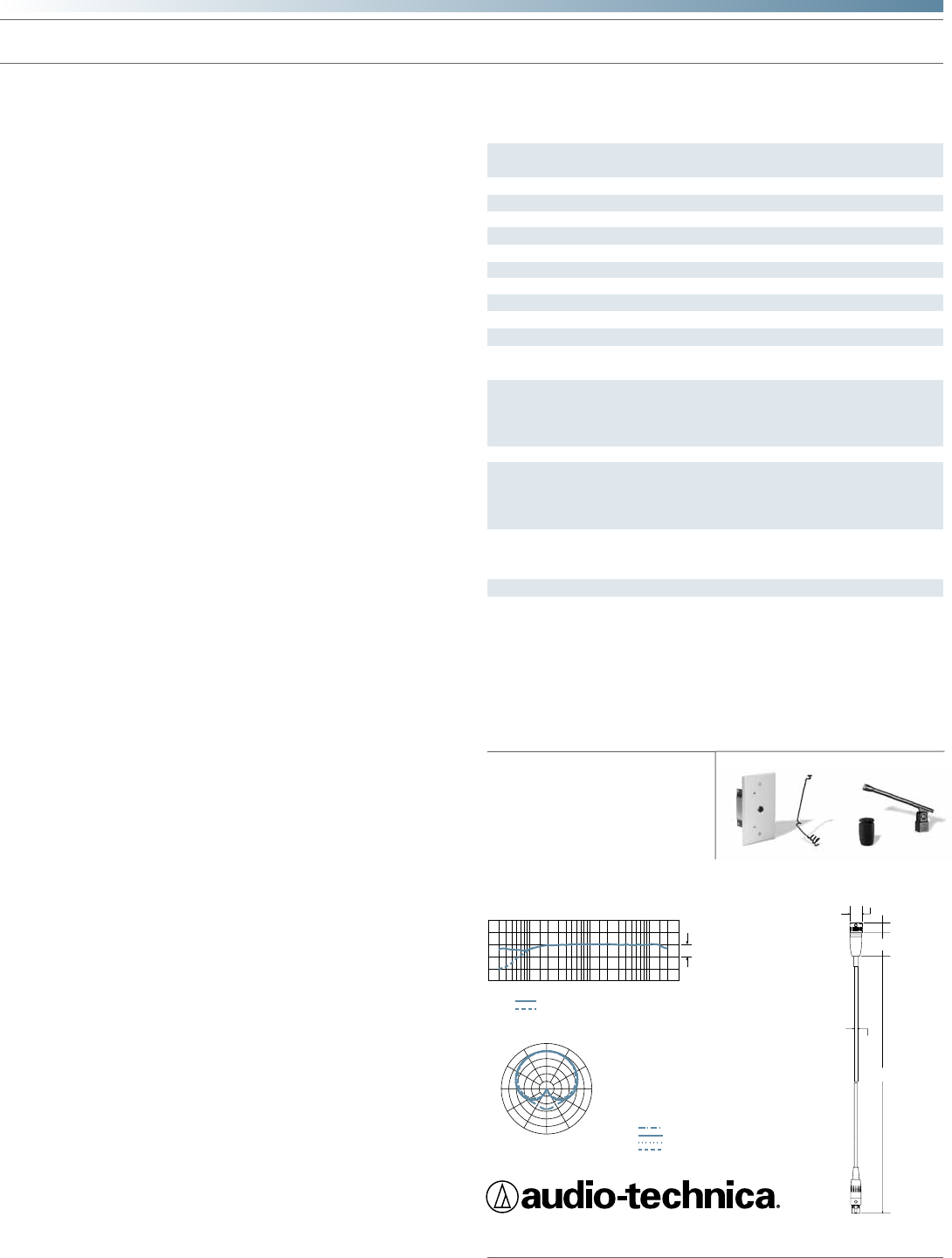
LEGEND
200 Hz
1 kHz
5 kHz
8 kHz
SCALE IS 5 DECIBELS PER DIVISION
240˚
180˚
210˚
270˚
300˚
330˚
0˚
150˚
120˚
90˚
30˚
60˚
12" or more on axis
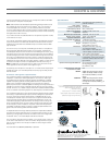
LEGEND
Frequency in Hertz
Response in dB
10 dB
100
50
200
10k
5k
1k
500
2k
20k
Roll-off
frequency response: 30–20,000 Hz
polar pattern
Fixed-charge back plate, permanently
polarized condenser
Cardioid
30-20,000 Hz
80 Hz, 18 dB/octave
–39 dB (11.2 mV) re 1V at 1 Pa
200 ohms
128 dB SPL, 1 kHz at 1% T.H.D.
102 dB, 1 kHz at Max SPL
68 dB, 1 kHz at 1 Pa
11-52V DC, 4 mA typical
Flat, roll-off; 0 dB/+10 dB gain setting
Microphone: 14 g (0.5 oz)
Power module: 97 g (3.4 oz)
Microphone: 34.0 mm (1.34") long,
12.2 mm (0.48") diameter
Power module: 71.0 mm (2.80") W x
115.5 mm (4.55") H x 36.0 mm (1.42") D
Power module: Screw terminals
7.6 m (25.0') long (permanently attached
to microphone), 3.2 mm (0.13") diameter,
2-conductor, shielded cable with TA3F-
type connector
UE-O omnidirectional (360°)
UE-H hypercardioid (100°)
UE-UL UniLine
®
(90°)
M12
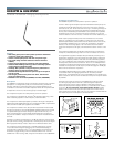
AT8534 wall/ceiling plate power module;
AT8451 steel hanger; AT8153 two-stage
foam windscreen; AT8438
5
/
8
"-27 stand
adapter
AT8534 wall/ceiling plate power module;
AT8451(WH) steel hanger; AT8153(WH)
two-stage foam windscreen; AT8438
5
/
8
"-27
stand adapter
Element
Polar pattern
Frequency response
Low frequency roll-off
Open circuit sensitivity
Impedance
Maximum input sound level
Dynamic range (typical)
Signal-to-noise ratio
1
Phantom power requirements
Switches
Weight
Dimensions
Output connector
Cable
Optional interchangeable elements
Audio-Technica case style
Accessories furnished
U853PM
U853PMW
0.48"
12.2 mm
10.0 mm
0.39"
24.0 mm
0.95"
0.13"
3.2 mm
25'
7.6 m
Connect the TA3F-type connector from the microphone's cable to the TA3M-
type connector in the power module plate.
Note: Audio-Technica has developed a special RFI-shielding mechanism that
is an integral part of the connectors in the UniPoint
®
line. If you remove or
incorrectly replace the connector, you may adversely affect the unit's RFI
immunity. Audio-Technica offers a crimp tool (ATCT) and RFI shields that enable
you to shorten the cable and correctly reinstall the connector while maintaining
the highest level of RFI immunity.
If you need to shorten the cable between the microphone and power module,
it can be done two ways:
a. To maintain original RFI shielding (see note above), the TA3F-type connector
can be removed from the cable end, the cable shortened and the connector
replaced using Audio-Technica's available crimp tool and RFI shield for TA3F-
type connector.
b. If RFI immunity is not required, the TA3M-type connector on the plate can
be removed and discarded (save the back nut and washer). Assemble the
included plastic ferrule into the hole left from the TA3M-type connector, using
the washer and nut from the connector to secure the ferrule. Cut the cable to
the desired length plus a few inches. Thread the cable through the ferrule and
tie a knot in the cable behind the ferrule to secure it. Carefully strip the ends
of the cable and connect the wires to the terminals formerly occupied by the
TA3M-type connector. Maintain color coding (Shield - S, Yellow - Y, Red - R) and
connect the microphone wires to the appropriate terminal screws (Fig. 3).
Note: The cable has two red wires and two yellow wires. Twist the two red
wires together and the two yellow wires together (Fig. 4).
Avoid leaving the microphone in the open sun or in areas where temperatures
exceed 110° F (43° C) for extended periods. Extremely high humidity should
also be avoided.
Architect’s and Engineer’s Specications
The microphone shall be a xed-charge condenser designed for permanent
installation. It shall have a cardioid polar pattern with a uniform 120° angle
of acceptance and a frequency response of 30 Hz to 20,000 Hz. It shall be
capable of accepting optional interchangeable elements for additional polar
patterns. The microphone shall operate from an external 11V to 52V DC
phantom power source. It shall be capable of handling sound input levels up to
128 dB with a dynamic range of 102 dB. Nominal open-circuit output voltage
shall be 11.2 mV at 1 V, 1 Pascal. Output shall be low impedance balanced (200
ohms). It shall offer outstanding rejection of radio frequency interference (RFI).
The microphone shall have a 7.6 m (25') permanently attached miniature cable
terminating in a special TA3F-type output connector designed to optimize RFI
immunity. The output connector shall connect to a TB3M-type jack on the
included power module. Output connections on the power module shall be
screw terminals. The plate power module shall be designed to mount over
a standard single-gang metal electrical box for ceiling or wall mounting. The
power module shall contain a switch to permit choice of at response or 80
Hz low-frequency roll-off. In addition, the power module shall incorporate a
switchable +10 dB gain setting. The power module face plate shall be semi-
gloss white and mounting screws shall be included.
An adjustable steel wire hanger shall be provided for suspended installations.
The steel wire hanger shall attach to the microphone body and allow for the
positioning of the microphone without the need for tools. A two-stage foam
windscreen and a
5
/
8
"-27 stand adapter shall also be included.
The microphone shall be a hanging design, with overall length of 34.0 mm
(1.34") and a head diameter of 12.2 mm (0.48"). Weight shall be 14 grams
(0.5 oz) without cable. The microphone cable and steel hanger shall be
black [white].
The Audio-Technica U853PM [U853PMW] is specied.
343