


Operation
I
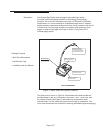
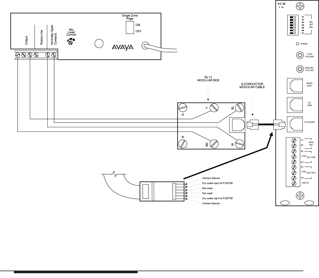
Figure 5. Typical Connections to a LUPCM Paging System Controller Unit
Figure 5 shows the wiring diagram for connecting microphones to an Avaya
LUPCM Paging System Controller Unit.
To make a short page, press and hold the larger, momentary contact push-button. To make a
longer page, press the smaller locking push-button; when the page is over, press this button
again to deactivate. Use the DTMF pad to select zone addresses or implement paging
features; refer to your Amplifier Manual for zone options.
The three LEDs on the front panel show paging status. A flashing yellow LED indicates a
long term page. The red LED indicates a busy condition on the system. The green LED
indicates that the microphone is on and ready to initiate a page (even when the unit is
paging).
The volume can be adjusted for an individual microphone by using the screwdriver-
accessible output level at the back panel (see Figure 2).
Page 7 of 7