


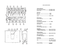
CH2 (4): Controls the input level (volume) of the microphone connected to Input CH 2 (13).
Zero is the lowest (quietest) setting, 10 is the highest (loudest).For the best possible sound and
lowest noise increase the input level control until the input LED lights occasionally.
OUTPUT LEVEL LED INDICATORS (5)
For the best sound increase the INPUT LEVEL of CH1 (3) and/or CH2 (4) so that the
corresponding PEAK LED indicator (5) flashes red occasionally during the loudest parts of
what you are recording. If the indicator does not light it means that the input (volume) level is
too low and the sound may be accompanied by background hiss. If the indicator is lit
continuously it means that the input (volume) level is too high and the sound may be distorted.
Monitor the sound with headphones and adjust the input levels for the best sound.
OUTPUT SELECT CH A (6) and CH B (7)
By setting the OUTPUT SELECT switch (6) and/or (7) to L the sound of any microphone
plugged into the corresponding INPUT CH1 (12) and/or CH2 (13) will be sent to OUTPUT
CH L (14). If using the UNBALANCED OUTPUT (16) the sound of this microphone will be
sent to the left channel.
By setting the OUTPUT SELECT switch (6) and/or (7) to C the sound of any microphone
plugged into the corresponding INPUT CH1 (12) and/or CH2 (13) will be sent to OUTPUT
CH L (14) and OUTPUT CH R (15). If using the UNBALANCED OUTPUT (16) the sound
of this microphone will be sent to the left and right channels.
By setting the OUTPUT SELECT switch (6) and/or (7) to R
the sound of any microphone
plugged into the corresponding INPUT CH1 (12) and/or CH2 (13) will be sent to OUTPUT
CH R (15). If using the UNBALANCED OUTPUT (16) the sound of this microphone will be
sent to the right channel.
MONITOR CONTROL (11) and MONITOR OUTPUT (10)
The MONITOR control (11) adjusts the volume level of headphones connected to the MONITOR
output (10). Zero is the lowest (quietest) setting, 10 is the highest (loudest).
MONITOR SELECTOR SWITCH (#9)
Normally, set the MONITOR selector (9) to position L/R. In the L/R position you will monitor
the sound of all connected microphones using either stereo or mono headphones. If you only
want to hear the output from CH L, use stereo headphones and set the switch to position L.
Or, if you only want to hear the output from CH R, use stereo headphones and set the switch
to position R.
LIMITER SWITCH (8)
After setting the Input Levels, turn this switch to ON. The limiter circuit reduces possible
overload distortion from very loud sound levels without affecting normal sound levels. If you
prefer the overall sound quality of the mixer without the limiter circuit engaged leave the switch
OFF.
INPUT CH 1 (12) and CH 2 (13)
Connect the output of a microphone or wireless receiver to INPUT CH 1 (12) and/or CH 2
(13). The inputs accept a standard 3-pin male XLR connector equipped cable. Push the
connector into the input jack until it locks. To remove the connector, press the PUSH tab and
pull out the connector. For a more detailed description of how INPUT CH 1 (12) and
INPUT CH 2 (13) work see OUTPUT SELECT above.
OUTPUT CH A (14) and CH B (15)
Connect a cable from OUTPUT CH A (14) and/or CH B (15) to the mic or line input of your
video camera or audio recorder. The outputs accept a standard 3-pin female XLR connector
equipped cable. Push the cable connector into the output jack until it locks, and to remove the
connector press the release tab on the connector and pull out. For a more detailed
description on how OUTPUT CH A (14) and CH B (15) work see OUTPUT SELECT
above.
UNBALANCED OUTPUT (16)
This output is stereo (dual-channel). It is recommended to use a stereo-to-stereo mini-
cable (not supplied) from the UNBALANCED OUTPUT (16) to the mic or line input of your
video camera or audio recorder. The UNBALANCE OUTPUT (16) is designed for video
cameras or audio recorders, which have mini-jack microphone or line inputs. Because the
FMX-20 has low-impedance XLR inputs and a mini-plug output, users of mini DV cameras
that have mini-plug microphone inputs can now use high-quality microphones with XLR
outputs. For a more detailed description on how the UNBALANCED OUTPUT (16)
works see OUTPUT SELECT above.
DC 12V Input (17)
For external powering of the mixer connect a power supply to this input. Maximum rating
of the power supply should not exceed 12 volts, 350mA.