


6
7
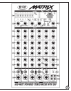
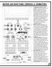
MATRIX-600 FRONT PANEL CONTROLS & CONNECTORS
MASTER SECTION
1. Blue POWER LED: indicates that the Matrix-600
is turned on.
2. MASTER VOLUME: controls overall volume of
the Matrix-600.
3. Red PROTECT LED: indicates when the Matrix-600
enters protection mode. Also lights briefly at
TURN-ON and when speakers are muted.
4. MASTER OUTPUT LED meter: Five LEDs per
channel help you set the output volume properly.
The top red LED (+3dB) may blink occasionally but
be sure to avoid constant blinking of this red LED to
prevent heavy overload of the speaker system;
allowing you to achieve clean sound and prolong
the life of your speaker system.
5. 7-band MASTER EQ: Use to fine-tune the sound of
your system. The Matrix-600 offers +/-6dB
adjustment range at center frequencies: 63Hz,
160Hz, 400Hz, 1kHz, 2.5kHz, 6.3kHz, 16kHz.
DSP SECTION
6. DSP LEVEL: Controls the overall volume level of the
built-in digital effects.
7. DIGITAL EFFECTS: The MATRIX-600 features sixteen
unique DSP effects settings best designed to suit your
musical needs. Select any one of these effects to be
added to your mix:
X-FACTOR (shifting the pitch of your signal up and
down), FLANGE, FLANGE REV, FLANGE DEL, HALL,
ROOM, PLATE 1, PLATE 2, VOCAL REV, DELAY,
ECHO 1, ECHO 2, ROTARY SPKR, ROTARY REV,
CHORUS & TREMOLO.
8. DIGITAL EFFECTS ACTIVE: Turns ON and OFF
DSP effects.
9. DIGITAL EFFECTS TO RECORD: Adds or removes DSP
effects from the RECORD outputs on the rear panel.
This switch works only when the DIGITAL EFFECTS
ACTIVE is turned ON.
10. PARAMETERS: Changes the parameters of DSP effects,
so you can alter the sound of your mix. Set and
range of parameters depends on which effect is active.
MONITOR SECTION
11. LEVEL: C ontrols the overall level of the output signal
of the mono MONITOR output on the rear panel. It is
proportional to each channel’s setting by that
channel’s MONITOR LEVEL. Also controls the
HEADPHONES output when the headphones are
switched to MONITOR as a source on the rear panel.
12. EFFECTS TO MONITOR: Controls the level of the DSP
effects added to the mix on the MONITOR output. It
affords flexibility of monitoring the mix without
added effects, or with lesser effects while providing
the full power of the DSP effects to the MAIN outputs.
INPUTS 1 to 4
13. MIC INPUT: Combo XLR and 1/4” TRS connector for
balanced dynamic or condenser microphones.
14. 48V PHANTOM POWER: There are two switches
recessed behind the front panel which turn 48Vdc
phantom power ON and OFF. Phantom power is
used by condenser microphones and should not be
used when dynamic microphones are connected.
These switches are shared between channels 1 and
2, and between channels 3 and 4. Connect similar
type microphones to these channels (i.e. do not
connect dynamic MIC to channel 2 when a
condenser MIC is connected to channel 1 and
phantom power on channels 1 and 2 is turned ON).
When phantom power is activated, the red LED just
above the switch illuminates. These switches are
recessed to avoid accidental activation and loud
clicking sounds during your performance, yet they
are easily accessible. The Matrix-600 uses high-
quality phantom power with full 48Vdc voltage to
accommodate virtually any condenser microphone.
Turn the MASTER VOLUME down completely before
activating the PHANTOM POWER to avoid loud
clicks from your speakers.
15. LINE INPUT: Balanced 1/4” TRS connector for mono
line-level sources.
16. VOLUME: Controls the signal volume of each
individual channel.
17. PAN: Controls routing the mono signals to either Left
or Right speakers. Place PAN in a neutral position to
keep source centered. Turning this control from center
moves the image of the performer on this channel
towards one side. Either fully clockwise or counter-
clockwise will solely place the performer in either the
right or left side.
INPUT 5
18. MIC/INSTRUMENT INPUT: Combo XLR and 1/4”
TRS connector is used to connect two different
sources. XLR is balanced low impedance input for
dynamic microphone. 1/4” TRS is mono
unbalanced high impedance input for a wider
range of sources, such as an acoustical instrument
with a pick up.
19. STEREO LINE INPUT: 1/4” TRS connector is a stereo