


ENGLISH
XENYX 1204/1204FX User Manual
10
ENGLISH
XENYX 1204/1204FX User Manual
11
CONTROL ROOM OUTPUTS
The control room output is normally connected to the
monitor system in the control room and provides the stereo
mix or, when required, the solo signal.
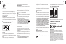
Voltage supply, phantom power and fuse2.4.2
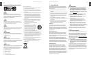
Voltage supply and fuseFig. 2.15:
FUSE HOLDER
The console is connected to the mains via the cable supplied
which meets the required safety standards. Blown fuses
must only be replaced by fuses of the same type and rating.
IEC MAINS RECEPTACLE
The mains connection is via a cable with IEC mains
connector. An appropriate mains cable is supplied with
the equipment.
POWER
Use the POWER switch to power up the mixing console.
PHANTOM
The PHANTOM switch activates the phantom power supply
for the XLR connectors of the mono channels which is
required to operate condenser microphones. The red
+48 V LED lights up when phantom power is on. As a rule,
dynamic microphones can still be used with phantom power
switched on, provided that they are wired in a balanced
configuration. In case of doubt, contact the microphone
manufacturer!
After the phantom power supply has been switched ◊
on, do not connect microphones to the mixer (or
the stagebox/wallbox). Connect the microphones
before you switch phantom power on. In addition, the
monitor/PA loudspeakers should be muted before
activating the phantom power supply. After switching
on, wait approx. one minute to allow the system
to stabilize.
Caution! You must never use unbalanced XLR ◊
connectors (PIN 1 and 3 connected) on the MIC
input connectors if you want to use the phantom
power supply.
SERIAL NUMBER
Please note the important information on the serial number
given in chapter 1.3.3.
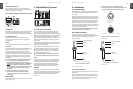
Digital Effects Processor3.
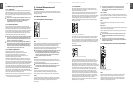
Digital effects module (only 1204FX)Fig. 3.1:
24-BIT MULTI-EFFECTS PROCESSOR
Here you can find a list of all presets stored in the multi-
effects processor. This built-in effects module produces
high-grade standard effects such as reverb, chorus, flanger,
delay and various combination effects. The integrated effects
module has the advantage of requiring no wiring. This
way, the danger of creating ground loops or uneven signal
levels is eliminated at the outset, completely simplifying
the handling.
These effect presets are designed to be added to dry signals.
If you move the FX TO MAIN control, you mix the channel
signal (dry) and the effect signal.
This also goes for mixing effects signals with the monitor
mix. The main difference is that the mix ratio is adjusted
using the FX TO MON control. Of course, a signal has to
be fed into the effects processor via the FX control in the
channel strip for both applications.
On the following page, you will find an illustration ◊
showing how to connect your foot switch correctly.
LEVEL
The LED level meter on the effects module should display
a sufficiently high level. Take care to ensure that the clip
LED only lights up at peak levels. If it is lit constantly, you
are overloading the effects processor and this could
cause unpleasant distortion. The FX control (AUX SEND 2)
determines the level that reaches the effects module.
PROGRAM
You can select the effect preset by turning the PROGRAM
control. The display flashes the number of the current preset.
To recall the selected preset, press the button; the flashing
stops. You can also recall the selected preset with the
foot switch.
Installation4.
Rack mounting4.1
The packaging of your mixing console contains two 19" rack
mount wings which can be installed on the side panels of
the console.
Before you can attach the rack mount wings to the mixing
console, you need to remove the screws holding the left and
right side panels. Use these screws to fasten the two wings
onto the console, being careful to note that each wing fits a
specific side. With the rack mount wings installed, you can
mount the mixing console in a commercially available 19"
rack. Be sure to allow for proper air flow around the unit, and
do not place the mixing console close to radiators or power
amps, so as to avoid overheating.
Only use the screws holding the mixing console side ◊
panels to fasten the 19" rack mounts.
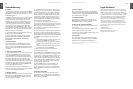
Cable connections4.2
You will need a large number of cables for the various
connections to and from the console. The illustrations below
show the wiring of these cables. Be sure to use only
high-grade cables.
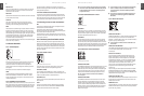
¼" TS connector for foot switchFig. 4.1:
Audio connections4.2.1
Please use commercial RCA cables to wire the 2-track inputs
and outputs.
You can, of course, also connect unbalanced devices to the
balanced input/outputs. Use either mono plugs, or ensure
that ring and sleeve are bridged inside the stereo plug (or
pins 1 & 3 in the case of XLR connectors).
Caution! You must never use unbalanced XLR ◊
connectors (pin 1 and 3 connected) on the MIC inputs
if you intend to use the phantom power supply.
XLR connectionsFig. 4.2:
¼" TS connectorFig. 4.3:
strain relief clamp
sleeve
tip
sleeve
pole 1/ground
tip
pole 2
The footswitch connects both poles momentarily
1/4" TS footswitch connector
input
output
For unbalanced use, pin 1 and pin 3 have to be bridged
1 = ground/shield
2 = hot (+ve)
3 = cold (-ve)
12
3
1
2
3
Balanced use with XLR connectors
Strain relief clamp
Sleeve
Tip
Sleeve
(ground/shield)
Unbalanced ¼" TS connector
Tip
(signal)