


11
ULTRACOUSTIC ACX1000
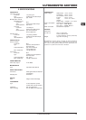
Fig. 4.3: 1/4" stereo jack connector
4.3 MIDI connection
The MIDI standard (Musical Instruments Digital Interface) was
developed in the early 80’s to enable electronic musical
instruments of different makes to communicate with each other.
Over the years the range of MIDI applications has constantly
expanded, and today it is completely normal to network entire
recording studios using the MIDI standard.
At the heart of this network we find a computer loaded with a
sequencer software that controls not only the keyboards but
also effects and other peripheral devices. In such a studio you
could control your ULTRACOUSTIC in real time from a computer.
In particular, when playing live gigs you can use a MIDI
footcontroller to control both the effect parameters and channel/
effect changes on your ULTRACOUSTIC.
The MIDI connector on the rear of your ULTRACOUSTIC is an
internationally standardized 5-pin DIN jack. To connect your
ULTRACOUSTIC to other MIDI equipment, you need a dedicated
MIDI cable, which is commercially available in various lengths.
However, you can solder your own cables using 2-conductor
shielded cables (e.g. microphone cables) and two rugged 180°
DIN plugs: pin 2 (center) = shield; pins 4 and 5 (right and left of
pin 2) = internal conductor; pins 1 and 3 (the outer pins) are not
used. MIDI cables should not exceed a length of 15 meters.
Make sure that pin 4 is connected to pin 4, and pin 5
to pin 5 on both plugs.
MIDI IN: receives MIDI controller information. The receiving
channel can be set with the buttons UP and DOWN. On = Omni,
i.e. MIDI data are received and processed on all channels (see
section 3.2).
4. INSTALLATION
4. INSTALLATION
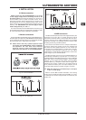
4.1 Mains connection
Please ensure that the ULTRACOUSTIC is set to the
correct supply voltage before connecting the unit to the
AC power system! Three triangular markings can be found on
the fuse holder at the AC power connection socket. Two of
these three triangles will be aligned with one another. The
ULTRACOUSTIC is set to the operating voltage shown next to
these markings and can be switched over by twisting the fuse
holder by 180°. IMPORTANT: This does not apply to export
models designed only for 120 V~!
The mains connection of the ULTRACOUSTIC is made by using
the enclosed mains cable and a standard IEC receptacle. It meets
all of the international safety certification requirements.
4.2 Audio connections
Except for the MIC and LINE/INST. inputs and the DIRECT OUT,
the audio inputs and outputs of your BEHRINGER ULTRACOUSTIC
are on unbalanced connectors. Please use commercially available
RCA connectors for the TAPE inputs and outputs.
Please ensure that only qualified persons install
and operate the ULTRACOUSTIC. During installation
and operation the user must have sufficient
electrical contact to earth. Electrostatic charges
might affect the operation of the ULTRACOUSTIC!
Fig. 4.1: XLR connections
Fig. 4.2: 1/4" mono jack