


5 EUROLIVE B1220DSP User Manual
1. Introduction
◊ Please read this manual to familiarize yourself with the control
elements of the unit and its functions. After you have carefully read
this manual, keep it for future reference.
1.1 Before you get started
1.1.1 Shipment
Your B1220DSP was carefully packed at the assembly plant to assure secure
transport. Should the condition of the cardboard box suggest that damage may
have taken place, please inspect the unit immediately and look for physical
indications of damage.
◊ Damaged equipment should NEVER be sent directly to us.
Please inform the dealer from whom you acquired the unit
immediately as well as the trans port ation company from which you
took delivery. Otherwise, all claims for replacement/repair may be
rendered invalid.
◊ Please always use the original packaging to avoid damage due to
storage or shipping.
◊ Never let unsupervised children play with the B1220DSP or with
its packaging.
◊ Please dispose of all packaging materials in an environmentally
friendly fashion.
1.1.2 Initial operation
Be sure that there is enough space around the unit for cooling. To avoid
overheating, do not place the B1220DSP on top of power amps or near
radiators,etc.
The mains connection is made using the enclosed power cord and a standard IEC
receptacle. It meets all international safety certication requirements.
◊ Please make sure that all equipment is properly grounded at all times.
For your own safety, never remove or disable the ground conductor of
the unit or of the AC power cord.
Important note concerning installation:
◊ The sound quality may diminish within the range of powerful
broadcasting stations and high-frequency sources. Increase the
distance between the transmitter and the device and use shielded
cables for all connections.
1.1.3 Online registration
Please register your new BEHRINGER equipment right after your purchase
by visiting http://behringer.com and read the terms and conditions of our
warrantycarefully.
Should your BEHRINGER product malfunction, it is our intention to have it
repaired as quickly as possible. To arrange for warranty service, please contact
the BEHRINGER retailer from whom the equipment was purchased. Shouldyour
BEHRINGER dealer not be located in your vicinity, you may directly contact
one of our subsidiaries. Corresponding contact information is included in the
original equipment packaging (Global Contact Information/European Contact
Information). Should your country not be listed, please contact the distributor
nearest you. A list of distributors can be found in the support area of our website
(http://behringer.com).
Registering your purchase and equipment with us helps us process your repair
claims more quickly and eciently.
Thank you for your cooperation!
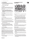
2. Control Elements and
Connections
(2) (4)(7) (8) (9)
(1)
(13) (5)
(3)
(11) (12) (6)
(10)
Fig. 2.1: Control elements and connections
(1) Power is supplied via an IEC connector. The matching cable is provided with
the unit.
(2) Use the POWER switch to turn on the B1220DSP. Before connecting the unit
to the power mains, ensure that the POWER switch is in OFF position.
◊ Attention: The POWER switch does not fully disconnect the unit
from the mains. To disconnect the unit from the mains, pull out the
main cable plug or appliance coupler. When installing the product,
ensure the plug or appliance coupler is readily operable. Unplug the
power cord completely when the unit is not used for long periods
of time.
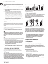
(3) Use the LEVEL control to adjust the signal gain of the MIC/LINE inputs.
Beforeyou connect or disconnect a signal source to or from one of the inputs,
please turn the corresponding control fully to the left. Once the signal
source is connected, increase the volume as desired by turning the control
clockwise. Always make sure that the CLIP LED (4) does not light up at all or
with signal peaks only.
Line-level signals:
Devices with high output levels (e.g. the outputs of mixing consoles or CD players)
only need little gain. In this case, the LEVEL control will mostly be positioned
somewhere in the area marked “LINE” (left half of the control range).
Microphone signals
Low-level microphone signals need more gain. When microphones are used,
thecontrol will be positioned in the MIC area (right half of the control range).
◊ We would like to draw your attention to the fact that extremely
loud sound levels may damage your hearing as well as your
headphones/loudspeakers. Turn the LEVEL control fully to the left
before you switch on the unit. Be careful to select a suitable volume
at all times.
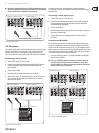
(4) The CLIP LED lights up when the input signal level is too high. In this case,
turn the LEVEL control (3) to the left until the LED goes out or only lights up
at peak levels.
(5) Use the MIC/LINE inputs (XLR connectors) for connecting audio signals.
(6) The LINE OUT XLR jack provides the signal with no additional gain applied
in order to connect another loudspeaker, for example. The output signal is a
mix of both input signals. (See Chapter 4.2 for more information on how to
use several loudspeakers)