


17
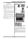
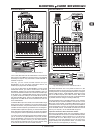
B-CONTROL FADER BCF2000-WH
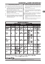
LED display of the push encoders:
OFF The LED circle remains off.
1d (1 digit): Only one LED lights up (standard setting).
1d- The LED circle operates similar to 1d, but when the
value is 0, no LED lights up.
2d The display of the LED circles occurs in two stages. If you
slowly turn the encoder from left to right, at first only one
LED lights up, and then the next LED lights up while the
previous LED goes out, and so on. This way, even the
slightest value changes can be accurately represented.
2d- Just like 2d, but when the value is 0, no LED lights up.
Bar Bar display: when the value is changed, all LEDs light up
successively (for volume etc.).
Bar- Just like bar display, but when the value is 0, no LED
lights up.
Sprd Spread: When the value is 0, the upper middle LED lights
up; when the value is increased, the LED circle gradually
lights up in both directions (left and right).
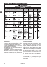
Pan In the middle position (value = 64), only the upper middle
LED is on. With lower values, the LED circle lights up
toward the left; with higher values, the LED circle lights
up toward the right (panorama adjustment).
Qual (Quality Q) has the opposite effect from spread: the LED
circle lights up gradually when you decrease the value.
This setting is used for indicating filter quality with
parametric equalizers.
Cut Cutoff is optimal for controlling the cutoff frequency of a
low-pass filter, for example on a synthesizer. When the
value is 0, all LEDs light up. The LEDs go out successively
as you increase the value.
Damp Damping: used for damping filters. When the value is 0,
the outer right LED lights up. If the values are increased,
the LED circle fans out from right to left until all LEDs
light up. This way, increasing damping is best represented
when a value goes up.
Fader functions:
Move If you move the fader by hand, it sends a new value directly.
In doing so, jumps in the parameter value may occur if the
current value doesnt correspond to the fader position. This
can sometimes happen because in this mode parameter
feedback doesnt cause fader movement.
P-UP Pick up: The fader ignores the parameter feedback.
However, value jumps are avoided because the fader only
sends values if the current value (different from the fader
setting) is exceeded.
Mot Motor: With parameter feedback, the motorized fader
engages automatically and always indicates the current
value.
Foot controller function:
Move The pedal immediately sends value changes. Value jumps
may result.
P-UP Pick-Up: The foot pedal become active and sends values
only if the set value is exceeded.
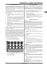
SWITCH-type elements:
SWITCH-type control elements have three different modes:
Toggle On, Toggle Off and Increment. Toggle On is similar
to a switching function (e.g. a light switch). Each time you press
the switch, the value sent alternates between the on value (set
by encoder 4) and the off value (set by encoder 5). This setting
is perfect for triggering drum loops from a sampler (press once =
start, press again = stop).
4. OPERATION
The Toggle Off mode corresponds to a momentary-contact
button, comparable to the switch of an electric door opener. The
on value is sent only as long as the button is pressed. After
releasing the button, the off value is sent. Use this control type
to trigger short sound FX or samples (similar to using a keyboard)
by sending Note On and Offs.
The Increment option only works for buttons, and only on CC,
NRPN and after touch command types. This mode lets you
gradually increase the controller value with each new keystroke.
Set up increment size using encoder 7. If you repeatedly press a
button, the value sent will be increased each time by the preset
amount selected here. If increment size is set to 10, values 0,
10, 20, 30 ... 110, 120, 0, 10 and so on will be successively sent
one after another. You can also enter negative values (e.g. -10)
to achieve a gradual decrease in the value. If you use encoders 4
and 5 to delineate the lowest and the highest value that are to be
sent, the values always stay within that range here as well. With
this function, you have the option to use your B-CONTROL to
control software buttons with more than two switch positions.
The value display activated using Push Encoder 8 is identical
for switch and continuous elements. If this value display is active,
the current value is indicated in the four-digit display when you
actuate a control element. The display shows the preset number
again as soon as you release the control element.
4.4 MIDI messages
Program Change:
With the encoders 3 and 4 you can select bank numbers. If a
MIDI device contains more than 128 presets/programs, first a
bank change command has to be sent. Even though this is a
controller command, it has to be sent before the program change
(and is therefore adjustable) since it is linked to the preset change.
If the bank select message is not needed, simply select off.
Encoder 5 selects the program number. If the selected control
element is a control dial (continuous type), the program
number is directly selected when turning the dial. Pressing
the switch directly selects the assigned program number.
This can be useful if you always want to start from the same
preset.
Control Change CC:
A control change consists of a controller number and its respective
value. Encoder 3 sets the controller number. With buttons, different
values can be sent when pressing and releasing (to be set with
encoders 4 and 5). This function is useful if fixed parameter
settings are to be sent.
With faders and control dials (continuous type), the value range
can be determined by using encoders 4 (minimum value) and 5
(maximum value).
+ Alternatively, you can invert the value scale by assigning
127 as the minimum value and 0 as maximum value
(scale inversion). A classic application is the draw bar
control of virtual or digital organs or organ expanders.
If assigning controller 7 (volume) to the faders this way,
the signal becomes quieter when moving up the fader.
Moving down the fader is similar to moving out the draw
bars, and the volume increases.
NRPN:
A NRPN is needed if none of the 127 standardized controller
numbers are available for a certain function.
Encoder 3 selects the parameter number. For assigning mixer
faders, we recommend the high resolution (Absolute 14 bit),
provided that the control hardware/software supports it.
Note:
Of course, a note can only be assigned to one SWITCH element.
The note is set with encoder 3. Note C3 (C key) corresponds with
note number 60. Encoder 4 sets the note velocity (note volume).