


8
ULTRA-DI PRO DI4000
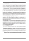
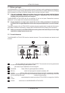
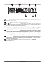
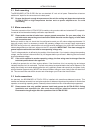
Fig. 1.2: Rear panel elements of the BEHRINGER ULTRA-DI PRO
8
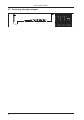
LINK. This is the unbalanced parallel output of the ULTRA-DI PRO. Connect this to the input of the
backline or monitor amplifier.
9
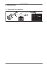
INPUT. Connect the source to this 1/4" jack to input the signal.
10
and
14
The -20 dB ATTENUATION switches greatly increase the operating range of the
ULTRA-DI PRO. From the low level signals of a high impedance guitar to the hot speaker terminals of a
PA amplifier. Depressing both will give 40 dB attenuation.
+ Only use the -20 dB switches if you are sure the ULTRA-DI PRO is clipping (overloading) and
not your mic pre-amp. Always use as little attenuation as possible to get the best possible
signal-to-noise ratio.
11
FUSE HOLDER/VOLTAGE SELECTOR. Please make sure that the voltage indicated on the unit matches
your local voltage, before you attempt to connect and operate the VINTAGER AC112. Blown fuses may
only be replaced by fuses of the same type and rating. Some models allow for inserting the fuse holder
in two different positions, in order to switch over from 230 V to 115 V operation, and vice versa. Please
note that for 115 V operation outside Europe, you need to use a fuse of a higher rating (see
chapter 3 INSTALLATION). Use the enclosed power cord to connect the unit to the mains.
12
SERIAL NUMBER. Please take the time to complete and return the warranty card within 14 days of the
date of purchase, otherwise you will lose the right to the extended warranty. Or just use our online-
registration (www.behringer.com).
13
To provide maximum flexibility the ULTRA-DI PRO is also fitted with an unbalanced XLR INPUT
to connect the source.
1. INTRODUCTION