


6
PRO MIXER DJX400
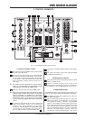
2. CONTROL ELEMENTS
happen, the MASTER signal is the only one that would be
heard. The MASTER signal is taken post MASTER LEVEL
control, whereas the signals from the two input channels
are pre CHANNEL faders and are routed to the MONITOR
section.
CH-1
CH-2
MASTER
L
R
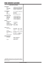
ON OFF OFF CH-1 "L" CH-1 "R"
OFF ON OFF CH-2 "L" CH-2 "R"
OFF OFF ON MASTER "L" MASTER "R"
ON ON OFF CH-1 "L" + CH-2 "L" CH-1 "R" + CH-2 "R
"
ON
OFF
ON
CH-1 "MONO"
MASTER "MONO"
OFF
ON
ON
CH-2 "MONO"
MASTER "MONO"
MONITOR SELECT Headphones output
Table 2.1: Selecting a signal with the Monitor Select button
2.4 MASTER section
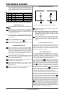
The LEVEL METER displays the signal level selected with
.
With this switch you determine whether it is the MASTER
or the MONITOR signal to be indicated on the LEVEL METER.
When the MONITOR LED lights up, it indicates the level
of the headphones signal.
+ In monitor mode, the LEVEL METER displays the
channel 1 signal on the left and the channel 2 signal
on the right.
This is the MASTER LEVEL control to adjust the output
volume at the MASTER output (see ).
The SURROUND control determines the intensity of the
XPQ 3D surround effect (see Chapter 2.7).
2.5 CROSSFADER section
The CF CURVE switch, to the right of the CROSSFADER,
allows you to put the fader control character in two stages.
In SOFT mode the volume is controlled evenly over the
whole slide. In SHARP mode the volume control is limited
to the outer portions of the slide. Naturally, a difference in
volume can occur when switching modes. Thus, dont
use this switch when the music is on!
The CROSSFADER is for crossfading between channels
1 and 2. The CROSSFADER, like the CHANNEL fader, is
also a professional 45 mm fader.
The TIME OFFSET LED indicates the synchronisation of
channels 1 and 2 (see Chapter 2.8).
The TEMPO DIFFERENCE LED displays tempo
differences between the signals from channel 1 and 2
(see Chapter 2.8).
The BEAT ASSIST button is for manually determining the
tempo for channels 1 and 2 (see Chapter 2.8).
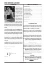
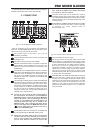
2.6 Front panel connectors
Fig. 2.2: Headphones and microphone connector
The MIC IN connector is the balanced jack input for a
dynamic microphone.
+ We strongly discourage the use of cheap plugs
for transmitting audio signals. Please use only
high-quality plugs as these provide the best
corrosion protection.
The PHONES OUT connector is for you to listen to bits of
music with your headphones (MONITOR signal). Your
headphones should have a minimum impedance of
32 ohms.
2.7 XPQ 3D surround effect
The XPQ 3D surround function is a built-in effect that puts the
finishing touches to your music and turns every gig into a real
experience. The widening of the stereo base makes for a livelier,
more transparent sound. You select the intensity of the effect
with the XPQ SURROUND control.
2.8 Auto BPM Counter
The PRO MIXER DJX400 auto BPM counter is an extremely
useful feature. It ensures smooth transition from one track to the
next, making your session an absolute success. It can calculate
the various tempi of tracks in bpm (beats per minute). The channel
1 and channel 2 BPM counter sections are identical.
Each channels DISPLAY indicates the track tempo. Several
tempo changes in one track would produce a constant display
of various BPM values and thus lead to unnecessary confusion.
Thats why the beat counter sections each have a SYNC LOCK
button that can be used during the song to limit the range of
possible tempo values. This makes sense if the counter has
already calculated a realistic value. You can do the same thing
manually with the BEAT ASSIST button . Pushing this button
at least three times in sync with the songs tempo results in the
calculated tempo appearing in the DISPLAY. The BEAT ASSIST
and SYNC LOCK buttons are each equipped with a LED.
When you have limited the tempo of the tracks on both channels
with the SYNC LOCK or BEAT ASSIST buttons, the difference in
tempo from channel 1 and channel 2 is illustrated in the form of a
nine-character message on the TEMPO DIFFERENCE-LED .
The extent of the difference in tempo is indicated by a
corresponding swing to the right (the channel 1 signal is slower)
or to the left (the channel 2 signal is slower). When the middle
LED lights up, the tempi are the same. The TIME OFFSET LED
below that displays the channel 1 and 2 synchronisation.
Should the middle LED light up, the tracks are synchronised.
Should the display move to the left or right, either channel 1 or
channel 2 is not synchronised. The TEMPO DIFFERENCE and
TIME OFFSET displays are only active if the tempi of both channels
have been fixed in one of the ways described.