


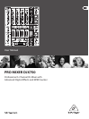

6 PRO MIXER DJX750 User Manual
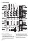
Each of the input channels features a 3-band equalizer (HI, MID and LOW) (4)
with kill characteristic. Thus, the signal can be attenuated to a much
greater extent (-32 dB) than it can be raised (+12 dB). This function can be
very useful when, for exmple, fading a frequency range out of a music track.
The overall level also depends on the EQ setting. Thus, should adjust ◊
the equalizer before setting the input gain with the GAIN control.
The 10-digit LED chains display the signal level of the input signals.(5)
Adjust the channel volume using the CHANNEL fader.(6)
Microphone channel1.2
The MIC IN connector is the balanced XLR input for your dynamic microphone.(7)
Set the volume of the microphone signal with the GAIN control in the (8)
MIC section.
There is a 3-band equalizer (HI, MID and LOW, no kill characteristic) (9)
in the microphone section. This allows you to ne-tune your voice to
adapt perfectly to your sound.
Activate the microphone channel using the MIC ON switch. The channel (10)
is active when the corresponding LED is lit.
The DJX750 is equipped with a talkover function, which works very simply: (11)
if you speak into the microphone while a track is running, the volume of
the music is automatically reduced, so that your voice is always “in front”.
The TALK control allows you to determine how much the music volume is
lowered (max. -24 dB). This function can come in handy when your own voice
needs to be prominently heard, as in when making an announcement etc.
MONITOR section1.3
The MONITOR signal is your headphones signal, allowing you to listen to music
without aecting the MASTER output signal.
When the MODE switch is in the “Split” position, channel PFL is located (12)
on the left side of the headphones, while the MASTER signal is on the
right side. In this case, the MIX control (see below) serves no function.
While in “Stereo” mode, you can use the MIX control to alternate
between MASTER signal and PFL.
When in “Stereo” mode, the MIX control lets you determine which signal (13)
can be heard via the headphones. When the control is turned to its left-most
position (CUE), you hear the PFL signal only; when the control is turned to
its right-most position, you hear the MASTER signal only. Alternating the
MIX control between the two end positions lets you dermine the relative
ratio between the two signals in your headphones.
The Level control determines the volume of the headphones signal.(14)
Connect your headphones using the PHONES OUT stereo connector. (15)
Your headphones should have a minimum impedance of 32 Ohms.
To select the PFL signal for the headphones, use the MONITOR CUE keys (16)
(CH-1 to CH-4, MASTER, FX). You can also select multiple signal sources
and listen to them simultaneously. LEDs on corresponding keys are lit
when a channel is routed to the headphones.
MASTER section1.4
The LEVEL METER displays the level of the MASTER signal.(17)
The MASTER fader allows you to adjust the output volume at the (18)
MASTER output (see (44)).
The MASTER BALANCE control for the MASTER output is for setting (19)
the stereo image.
The BOOTH LEVEL control adjusts the output level of the BOOTH output (20)
(see (45)).
Crossfader section1.5
ASSIGN A and ASSIGN B selectors let you determine which input signals are (21)
routed to CROSSFADER sides A and B. You can also alternate between these
two signals by using the CROSSFADER (see below).
The VCA controlled CROSSFADER is used to fade between the channels (22)
you have selected (see (21)). Like the channel faders, the crossfader section
is equipped with a professional 45-mm fader.
The TIME OFFSET LED indicates the synchronisation of tracks (see chapter 2.7).(23)
The TEMPO DIFFERENCE LED displays tempo dierences between the tracks (24)
(see chapter 2.7).
A 3-band kill switch is available for use with both the left and the right side (25)
of the crossfader (KILL A and KILL B respectively). Kill switches are used to
lower three separate frequency ranges (LOW, MID and HIGH) up to -32 dB.
When using the kill switch, the equalizer of ordinary DJ mixers usually
loses its functionality. Not the case with the DJX750: the EQs can be used to
achieve an even more pronounced lowering of a particular frequency range.
The CF CURVE control lets you alter the control characteristic of the (26)
crossfader between linear and logarithmic in an innite number of
steps. When set to linear, the crossfader engages directly proportionally
to the fader’s incremental movement. When set to logarithmic,
the fader’s movement yields higher volume increases as the fader
moves farther along its range of motion.
XPQ 3D surround eect1.6
The XPQ 3D surround function is a built-in eect that puts the nishing touch
to your music and turns every gig into a real experience. The widening of the
stereo base makes for a livelier, more transparent sound. You can determine
the intensity of the eect by using the SURROUND control (27), while the XPQ ON
switch (28) turns the XPQ eect on (the respective LED is lit).
Auto BPM counter1.7
The integrated auto BPM counter is an extremely useful feature. It ensures
smooth transition from one track to the next, taking a lot of the guesswork out.
It can calculate the various tempos of tracks in bpm (beats per minute). Both BPM
counter sections are identical and both show the BPM value of the two signals
routed to the crossfader. The LEDs located above the DISPLAYs 1 - 4 (29) indicate
which of the four input channels are routed to the respective BPM counter.
The tempo of the track assigned by using the ASSIGN A or ASSIGN B keys is shown
in the respective Display (30). Several tempo changes in one track would produce
a constant display of various BPM values and thus lead to unnecessary confusion.
That’s why the beat counter sections each have a SYNC LOCK button (31) that can
be used during the song to limit the range of possible tempo values. This makes
sense if the counter has already calculated a realistic value. You can do the
same thing manually with the BEAT ASSIST button (32). Pushing this button at
least three times in sync with the song’s tempo results in the calculated tempo
appearing in the DISPLAY. The Beat Assist and SYNC LOCK buttons are each
equipped with a LED.
When you have limited the tempo of the tracks on both channels with the
SYNC LOCK or BEAT ASSIST buttons, the dierence in tempo from both channels
is illustrated in the form of a nine-character message on the TEMPO DIFFERENCE-
LED (24). The extent of theT dierence in tempo is indicated by a corresponding
swing to the right (signal A is slower) or to the left (signal B is slower). When the
middle LED lights up, the tempi are the same. The TIME OFFSET LED (23) below that
displays the signal A and B synchronisation. Should the middle LED light up, the
tracks are synchronised. Should the display move to the left or right, the channels
are not synchronised. The TEMPO DIFFERENCE and TIME OFFSET displays are only
active if the tempi of both channels have been xed in one of the ways described.