


8
EURORACK MX2642A
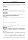
2.3 PSU (Power Supply Unit)
Any amplifier circuit is limited in its transient response by the available current. Every mixer has numerous line
level operational amplifiers (op-amps) inside. When being driven hard, many desks begin to show signs of
stress due to power supply limitations. Not so with the EURORACK. The sound will always stay clean and
crisp right up to the operating limits of the op-amps themselves, thanks to our generous 40 W external power
supply unit.
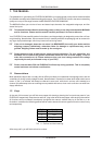
+ Do not connect the PSU to the EURORACK while the PSU is connected to the mains.
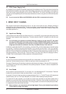
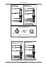
3. MONO INPUT CHANNEL
Each channel comes with a balanced line input on 1/4" jack, and an XLR mic input. Phantom powering is
switchable from the master panel (S36). The gain circuit has an unusually wide range from -50 dB to +10 dB,
obviating the need for mic/line switching. The crucial operating levels -10 dBV and +4 dBu are clearly and
accurately legended (P1).
3.1 Input Level Setting
Channel input level is determined by the GAIN control (P1). Use Solo/PFL (S14) to bring the channel input onto
the left and right bargraph meters respectively. This also sends the Solo/PFL-ed signal to the left and right
speakers.
+ For level setting (as opposed to localized listening) choose to use the mono PFL bus rather
than the post-fader (post-channel pan) stereo solo bus (CHANNEL MODE global switch S37 up).
Solo/PFL never interrupts the mix at the main recording outputs. It follows that aux sends and
subgroups must also be unaffected, since they contribute directly to the main mix.
In addition to switchable Solo/PFL (S14) metering, a channel LED (L15) illuminates when a channel is going
into overload. This takes its cue from three test points: Input, post-EQ and post-fader. This is very important,
especially when using extreme EQ settings or using a dynamics processor in an insert. In all cases the higher
level wins. You do not want the overload light to come on except very intermittently during a take or a mix. If it
does light persistently, reduce input gain. There is a steep Lo Cut (High Pass) filter (S2), slope @ 18 dB/Oct,
-3 dB @ 75 Hz, for reducing floor rumble, explosives, woolly bottom end etc.
3.2 Equalizer
All mono input channels are fitted with three-band EQ and a switchable Lo Cut filter for eliminating unwanted
subsonics. All three bands have up to 15 dB of cut and boost, with a centre detent for off.
The upper (P3) and lower (P6) shelving controls have their frequencies fixed at 12 kHz and 80 Hz respectively.
The midrange (P4) control is semi-parametric with a peaking response. Q fixed at 1 octave, sweepable from
100 Hz - 8 kHz (P5).
3.3 Aux Sends
All aux sends are mono and post-EQ. For aux sends 1 & 2, two dedicated pots (P7, P8) are used. These can
be taken from a point before or after the channel fader, i.e. pre or post (S9).
Aux sends 3 & 5, and 4 & 6 are serviced by two potentiometers (P10, P11). The SHIFT button (S12) determines
whether buses 3 and 4 or 5 and 6 are addressed. Aux sends 3/4/5/6 are always wired post-fader.
For almost all FX send purposes, you will want aux sends to be post-fader so that when a fader level is
adjusted, any reverb send from that channel follows the fader. Otherwise, when the fader is pulled down, the
reverb from that channel would still be audible. For cueing purposes, aux sends will usually be set pre-fader.
i.e. independent of the channel fader and mute.
+ Most reverbs etc. sum internally the left and right inputs. The very few that dont may be driven
in true stereo by using 2 aux sends.
3. MONO INPUT CHANNEL