


13 EURORACK PRO RX1202FX User Manual
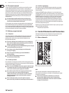
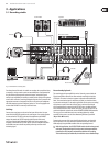
This illustration shows a typical arrangement for a live setup. Two vocal
microphones and the line outputs of a guitar and a bass amplier are connected
to the mono channels of the RX1202FX. A keyboard and a drum computer are
connected to the stereo channels. The power amplier in your sound system is
connected to the main outputs; equipment such as compressors, equalizers or
crossovers are located between the mixer and the amp in the signal path. If you
wish to make a live recording, you can connect your recording equipment
(in this case, a minidisk recorder) to the CD/TAPE outputs. A CD player that is
playing during intermissions is connected via the CD/TAPE inputs. If you connect
a recorder/player combo (e. g. a tape deck recorder), the CD/TAPE TO MIX switch
should not be pressed during a recording because this way the signal intended
for recording would be directly re-routed back to the mixing console, and then
back to the recorder... this would cause a feedback loop as soon as you hit the
record button. A loud, unpleasant, even painful sound would result.
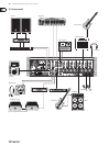
Connect two monitor speakers over a power amplier to the MON output which
musicians can then use on stage. Determine the amount of the input signals
(microphone, bass, keyboard, drum computer and guitar) in the mono and stereo
channels that are to be sent to the MON output by using the MON controller of
the corresponding channel.
4. Installation
4.1 Mains connection
AC POWER IN
The power supply is delivered through the power supply line to be found on
the backside. The connection complies with the required security regulations.
◊ Never connect the EURORACK to the power supply line while the latter
is already connected to the mains! Rather connect the console with the
power supply line before plugging it into the mains.
◊ Please note that the mixer warms up when in operation.
This is absolutely normal.
4.2 Audio connections
You will need a large number of cables for dierent applications.
The illustrations below show how the connectors should be wired.
Be sure to use only high-grade cables.
Please use commercial RCA cables to connect the CD/tape inputs and outputs.
You can, of course, also connect unbalanced equipment to the balanced
inputs/outputs. To do this, use either mono plugs or stereo plugs with the
ring and sleeve bridged (pins 1 and 3 in the case of XLR connectors).
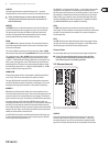
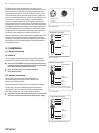
◊ Caution! Never use unbalanced XLR connectors (PIN 1 and 3 connected)
on the MIC input connectors when using the phantom power supply.
For unbalanced use, pin 1 and pin 3 have to be bridged
1 = ground/shield
2 = hot (+ve)
3 = cold (-ve)
input
12
3
output
1
2
3
Fig. 4.1: XLR connections
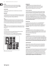
strain relief clamp
sleeve
tip
sleeve
(ground/shield)
Unbalanced ¼" TS connector
tip
(signal)
Fig. 4.2: ¼" mono plug
strain relief clamp
sleeve
ring
tip
sleeve
ground/shield
For connection of balanced and unbalanced plugs,
ring and sleeve have to be bridged at the stereo plug.
Balanced ¼" TRS connector
ring
cold (-ve)
tip
hot (+ve)
Fig. 4.3: ¼" stereo plug
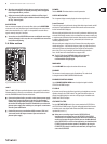
strain relief clamp
sleeve
ring
tip
sleeve
ground/shield
¼" TRS headphones connector
ring
right signal
tip
left signal
Fig. 4.4: Stereo plug for headphones connection