


8
EURODESK SL3242FX-PRO/SL2442FX-PRO
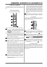
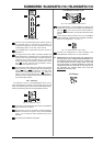
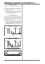
Use the routing switches for the subgroups to send the
subgroup signal to the main mix. You can route it to the left
stereo side (=LEFT pressed), to the right stereo side
(=RIGHT pressed) or to both (=LEFT and RIGHT pressed).
For example, when you have created a stereo submix
using subgroups 1 and 2, be sure to route group 1 to the
left and group 2 to the right side to maintain proper stereo
positioning. If it is a mono submix with just one subgroup,
route it to the left and right sides of the main mix to make the
signal audible on both sides.
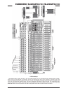
Fig. 2.10: Subgroup outputs 1 - 4
These four SUBGROUP OUT(PUTS) carry the signals of
the individual subgroups. For multi-tracking connect the
outputs to the inputs of a multi-track recorder (see chapter
4.1 Studio set-up).
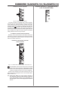
2.5 Mono out section for subwoofer applications
Using this auxiliary mono output you can route the main mix
signal to a separate power amp. The tunable low-pass filter
allows you to limit the signal content to the low-frequency range
to get a perfect subwoofer signal. This signal is mono because
very low frequencies disperse quickly, so there would be no
benefit to position this signal in the stereo mix.
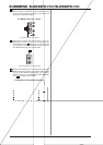
Fig. 2.11: Mono out fader and low-pass filter
The MONO fader controls the volume of the signal present
at the MONO OUT (see ).
The FREQ control adjusts the cut-off frequency of the low-
pass filter (30 to 200 Hz). Frequencies above cut-off are
filtered out when activated.
Use the LOW PASS FILTER switch to activate the filter
function (LED illuminates).
Fig. 2.12: Mono out connector
The MONO OUT connector provides the line-level mono
signal for connection to the inputs of a power amp or
active speaker. You can also use this output as a monitor
bus, e.g. to connect a headphone amplifier. In this case,
the signal should of course not be limited by the low-pass
filter.
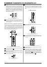
2.6 Main out section
Fig. 2.13: Main out fader
Use this high-precision MAIN fader to control the output
level of the main mix.
Fig. 2.14: XLR main out connectors
The MAIN OUT(PUTS) are balanced XLR connectors with
a nominal operating level of +4 dBu and provide the main
mix signal.
Fig. 2.15: Main out connectors and main insert
The MAIN OUT 1/4" TRS connectors outputs also provide
the main mix signal.
Like the channel inserts, the MAIN INSERT connectors
can be used to connect a dynamics processor or equalizer
for further processing of the mix signal. The MAIN INSERT
refers to the MAIN OUTs (XLR and 1/4" TRS connectors),
the MONO OUT (see ) and, if the MAIN switch in the
PHONES/CONTROL ROOM section is pressed, also to the
PHONES/CTRL ROOM output (see