


18
TUBE ULTRAFEX T1954
professional studios. Manufacturers try with ever new algorithms to get the most out of DSPs (Digital Signal
Processors), the heart of any digital system.
Still, many audio engineers, particularly old hands often prefer using both old and new tube-equipped devices.
As they want to use their warm sound character for their productions, they are ready to accept that these little
darlings produce a higher noise floor than modern, transistor-based devices. As a consequence, you can find
a variety of tube-based microphones, equalizers, pre-amps and compressors in todays recording and master-
ing environments. The combination of semiconductor and tube technologies gives you the additional possibility
of using the best of both worlds, while being able to make up for their specific drawbacks.
4.6.2 Tube history
Due to many patent litigations, it is difficult to determine exactly when the tube was born. First developments
in tube technology were reported between 1904 and 1906. It was a research task of that time to find a suitable
method for receiving and rectifying high frequencies. On April 12, 1905, a certain Mr. Fleming was granted a
patent for his hot-cathode valve which was based on Edisons incandescent lamp. This valve was used as a
rectifier for high-frequency signals. Robert von Lieben was the first to discover (probably by chance) that the
anode current can be controlled by means of a perforated metal plate (grid) one of the milestones in the
development of amplification tubes. In 1912, Robert van Lieben finally developed the first tube for the amplifica-
tion of low-frequency signals. Initially, the biggest problem was to produce sufficient volume levels, which is
why resonance step-ups (though impairing the frequency response) were used to maximize the attainable
volume. Later, the objective was to optimize the electroacoustic transducers of amplifiers in such a way that a
broad frequency band could be transmitted with the least distortion possible.
However, a tube-specific problem is its non-linear amplification curve, i.e. it modifies the sound character of the
source material. Despite all efforts to ensure a largely linear frequency response, it had to be accepted that
tube devices produce a bad sound. Additionally, the noise floor generated by the tubes limited the usable
dynamics of connected storage media (magnetic tape machines). Thus, a one-to-one reproduction of the audio
signals dynamics (expressed as the difference between the highest and lowest loudness levels of the program
material) proved impossible. To top it all, tube devices required the use of high-quality and often costly trans-
ducers and sophisticated voltage supplies.
With the introduction of semiconductor technologies in the field of audio amplification, it soon became clear
that the tube would have to give way to the transistor, as this device featured an enormously enhanced signal-
to-noise ratio, required a less complex power supply and yielded an improved frequency response. Plus,
semiconductor-based circuits can be realized much more easily - for less money.
Two decades later, the introduction of binary signal processing meant the beginning of a new era of recording
media that provided plenty of dynamic response and allowed for the loss-free copying of audio signals. As
digital media were enhanced, however, many people began to miss the warmth, power and liveliness they
knew from analog recordings. This is why purists still today consider digital recordings as sterile in sound.
4.6.3 Design and functional principle of tubes
Tubes can be roughly classified according to the number of electrodes they use. There are tubes with two,
three or five electrodes usually referred to as diodes, triodes or pentodes.
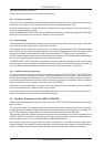
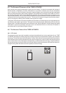
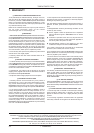
Fig. 4.2: Diode
The diode contains two electrodes in a vacuum glass bulb that have electrical connection to the outside. The
vacuum allows for a free movement of electrons. When one of the electrodes is heated up (= thus becoming a
cathode), it begins to emit electrons. When a positive DC voltage is applied to the other electrode (= anode),
the negative electrons start to migrate from the cathode to the anode. With reverse polarity between cathode
4. TECHNICAL BACKGROUND