


9 EURORACK UB1202FX/UB1002FX User Manual
+48 V
The red “+48 V” LED lights up when the phantom power is turned on.
Phantompower is required to operate condenser microphones and is activated
using the +48 V switch located above the +48 V LED.
◊ Connect microphones before you switch on the phantom power
supply. Please do not connect microphones to the mixer (or the
stagebox/wallbox) while the phantom power supply is switched on.
In addition, the monitor/PA loud speakers should be muted before you
activate the phantom power supply. After switching on, wait approx.
one minute to allow for system stabilization.
◊ Caution! You must never use unbalanced XLR connectors (PIN 1 and
3 connected) on the MIC input connectors if you want to use the
phantom power supply.
POWER
The blue POWER LED indicates that the console is powered on.
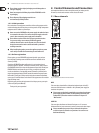
LEVEL INDICATOR
The 4-segment display accurately displays the relevant signal level.
LEVEL SETTING:
To correctly set the gains of the channels, rst set the LEVEL controls of the input
channels to their center positions. Then use the GAIN controls to increase the
input amplication until signal peaks show 0 dB on the level meter.
When recording to digital recorders, the recorder’s peak meter should not go into
overload. While analog recorders can be overloaded to some extent, creating only
a certain amount of distortion, digital recorders distort quickly when overloaded.
In addition, digital distortion is not only undesirable, but also renders your
recording completely useless.
When recording to an analog device, the VU meters of the recording machine
should reach approx. +3 dB with low-frequency signals (e.g. kick drum). Due to
their inertia VU meters tend to display too low a signal level at frequencies above
1 kHz. This is why, for example, a Hi-Hat should only be driven as far as -10dB.
Snaredrums should be driven to approx. 0 dB.
◊ The CLIP-LED’s of your EURORACK display the level virtually
independent of frequency. A recording level of 0 dB is recommended
for all signal types.
MAIN MIX
Use the MAINMIX fader to adjust the volume of the main out.
PHONES/CONTROL ROOM
Use the PHONES/CONTROL ROOM control to adjust the signal level of the
CONTROL ROOM and PHONES outputs.
CD/TAPE TO MIX
When the CD/TAPE TO MIX switch is pressed, the CD/tape input is assigned to
the main mix providing an additional input for tape machines, MIDI instruments
or other signal sources that do not require any processing.
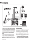
CD/TAPE TO CTRL
Press the CD/TAPE TO CTRL switch if you want to monitor the CD/tape input via
the CTRL ROOM and PHONES outputs. A typical studio application of this function
is recording music into a digital audio workstation (DAW) with simultaneous
reproduction (see ch. 3.1).
◊ If you are recording a signal via the TAPE OUTPUT and wish to listen to
this simultaneously via the CD/TAPE INPUT, do not use the CD/TAPE TO
MIX switch. Doing this would create a feedback loop, since the signal
would be routed, via the main mix, back to tape via the TAPE OUTPUT.
To monitor the CD/TAPE INPUT, use the CD/TAPE TO CTRL switch to
assign the tape signal to the monitor(s) or headphones. This will avoid
the tape signal being routed to the TAPE OUTPUT.
FX TO CONTROL
If you want to monitor only the eects signal in your headphones or monitor
speaker(s), press the FX TO CTRL switch. Now the signal of the eects processor
can be monitored alone, and the main mix and/or CD/tape signal is no longer
present on the phone and control room outputs.
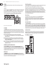
2.5 Digital eects processor
PROGRAM
(
PUSH
)
FX TO MAIN
REVERB
00
–
39
ER
/
DLY
40
–
59
MOD
60
–
73
PITCH
74
–
79
MULTI
80
–
99
0
+
20
CLIP
SIG
Fig. 2.5: Eects section
100 FIRST-CLASS EFFECTS
The EURORACK UB1002FX/UB1202FX features a built-in digital stereo eects
processor. This eects processor oers a large number of standard eects such as
Hall, Chorus, Flanger, Delay and various combination eects. Using the FX control,
you can feed signals into the eects processor. The integrated eects module has
the advantage of requiring no wiring. This way, the danger of creating ground
loops or uneven signal levels is eliminated at the outset, completely simplifying
the handling.
SIGNAL AND CLIP LED
The SIGNAL LED on the eects module shows the presence of a signal whose
level is high enough. This LED should always be on. However, make sure that the
CLIP LED lights up only sporadically. If it is lit constantly, you are overdriving the
eects processor, which leads to unpleasant distortion. If this occurs, turn the FX
controls down somewhat.
PROGRAM
The PROGRAM control has two functions: by turning the PROGRAM control,
you dial the number of an eect. The number of the preset you just dialed up
blinks in the display. To conrm your selection, press the PROGRAM control;
theblinking stops.
FX TO MAIN
The FX TO MAIN control feeds the eects signal into the main mix. If the control
is turned all the way counterclockwise, no eects signal is present in the sum
signal of the mixing console.
The appendix contains an overview of all presets of the multi eects processor.