


8 9X32 PRODUCER DIGITAL MIXER Quick Start Guide
X32 PRODUCER DIGITAL MIXER Getting Started
Mixer Operational Overview
Welcome to the X32 PRODUCER digital mixing
console QuickStart Guide! This document will give
you an overview of the basic operations of the
mixer, allowing you to get up and running quickly.
Whilereading through the information in this
document, we encourage you to experiment with the
console’s dierent screens and controls. The console’s
user interface was designed to be extremely easy
to navigate through and learn. Inaddition to this
Quick Start Guide, thereis anEnglish user manual
available as a PDF downloadfrom behringer.com.
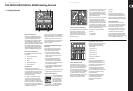
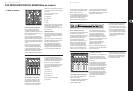
General user interface operation
The X32 PRODUCER user interface is divided into ve
majorsections:
(1) Channel Strip and Monitoring
(2) Input Channels
(3) Display
(4) Group/Bus/Main Channels
(5) Various Assignments
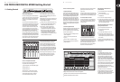
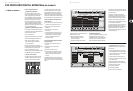
View buttons rule
Throughout the top panel of the console,
youwillnd small buttons labeled View. Press these
buttons to immediately switch the console’s large
color display (known as the Main Display) to show
information related to the section whose View
button you have just pressed.
For example, if you are editing the equalizer
and feel like seeing a large display of the EQ
frequency response curve or corresponding EQ
parametervalue, simply press the adjacent View
button in the EQ section. If you need to check where
the monitor signal is being routed, simply press the
View button next to the Phones Level knob and the
main display will show the details.
With the View button approach of the X32 PRODUCER
console, there is almost never a need to drill down
through multiple menu pages, since the View buttons
will always take you directly to the relevant screen.
Tip: The Setup/Global tab on the main display allows
preferences for the behavior of View and Select
buttons to be adjusted.
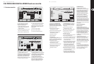
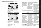
Customizing the X32 PRODUCER through the
Utilities page
Press the Utility button, located to the right of
the main display, to bring up useful functions in a
“context-sensitive” manner. For example:
• When you are adjusting the equalizer of a
console channel, pressing the Utility button
will oer copying, pasting, loading or saving of
equalizersettings
• Pressing the Utility button while holding a
channel select button depressed will present
a naming screen where you can customize the
channel’s appearance on both the main display as
well as the small channel display
• On the Routing pages, pressing the Utility button
will oer loading or saving dierent presets of
routing scenarios
• In the Scenes menu, pressing the Utility button oers
copying, loading, saving or naming consolescenes
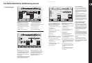
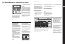
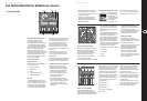
Sometimes there is more to say
Some of the individual pages
on the main display contain
more adjustable parameters
than can be controlled by
the 6 rotary push encoders
located beneath it. In these
cases there is a small page
number indication, e.g. “1/2”. Simply press the Layer
Up/Down buttons to switch between layers.
Dir 05
Dir 06
Key In
Source
Select
1 2
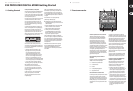
Section 1: Channel Strip and Monitoring
The X32 PRODUCER’s channel strip oers dedicated
controls for the most important processing
parameters of the currently selected channel.
To adjust controls for a given channel strip,
simply press the Select button on the desired
input or output channel.
Certain sections of the channel strip (such as the
low cut lter, noise gate, EQ and compressor)
contain a respectively labeled button that can be
pressed to switch the specic eect on and o.
Thebutton illuminates to show the eect is active,
and goes dark when bypassed.
Within the channel strip, the rotary control knobs
are surrounded by an amber LED collar that
indicates the parameter’s value. Whenever this
backlit knob is turned o, it indicates that this
specic control/parameter is not available for the
selected channel type. For example, if an output
bus is currently selected, the LED collar and the
gainknob are turned o, because there is no input
gain to be controlled on an output bus.
The channel strip consists of the following
sub-sections:
• Cong/Preamp
• Gate, Dynamics
• Equalizer
• Main Bus
Each of these subsections correspond to the
processing steps of the currently selected channel,
and they each have their own View button that,
when pressed, switches the Main Display to a page
displaying all related parameters for thatsubsection.
Monitoring and Talkback
There are two separate Level controls in this
section, one for the headphone output located at
the front of the console, and a second one for the
monitor outputs located on the rear panel.
Press the section’s View button to edit various
monitoring preferences, such as the input source
forthe phones bus and the monitor outputs.
This section also contains independent Talkback
buttons (A and B). Press the View button next to
the Phones Level knob, then press Page Select right
to access the Talkback A and B edit pages.
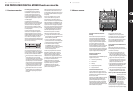
Section 2: Input Channel Banks
You will nd a select button on top of every
channel that is used to direct the control focus of
the user interface, including all channel related
parameters (channel strip and main display),
tothat channel. Please note that at any time,
there is exactly onechannel selected (either Input
Ch 1-32, Aux 1-6/USB, FXReturns 1L-4R, Mix Bus
1-16, Main LR/C, orMatrix 1-6). DCA Groups
(digitally controlled amplier) cannot be selected
because they control a number of assigned
channels rather than one specic channel.
The Input Channels section of the console is
locatedon the left hand side, and oers 8 separate
input channel strips. These 8 channel strips
represent six separate layers of inputs for the
console, including:
• Input Channels 1-8
• Input Channels 9-16
• Input Channels 17-24
• Input Channels 25-32
• Aux Inputs 1-6/USB playback
• Eects Returns
Press any of the correspondingly labeled layer
buttons on the left side of the console to
switch the input channel bank to any of the six
layers listed above. The button will illuminate,
reminding you which layer is active.
Two more layers (Bus Master 1-8 and 9-16)
are also oered, allowingyou to adjust the
levels of the 16 Mix Bus Masters, which is useful
when you wish to include Bus Masters into
DCA Group assignments.
On each fader strip you will nd a motorized
100mm level fader, Mute and Solo buttons,
aGate indicator, an input level meter,
Compressorindicator, and the channel
selectbutton.
(EN) Getting Started
(1) (3) (5)
(4)(2)