


11 XENYX XL3200/XL2400/XL1600 User Manual
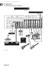
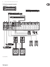
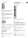
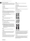
4.7 FX/Mon/Aux sends
FX 1 and 2
The FX outputs 1 and 2 provide the signals of the eects buses 1 and 2.
Thesesignals may be sent to external eects processors and are routed back over
the AUX-RETURN inputs or separate input channels, for example.
MON 1 and 2
The monitor outputs 1 and 2 provide the signals of the monitor buses.
Thesesignals may be be sent to stage loudspeakers. To prevent interference due
to the long cables being used between stage and mixing console, the outputs
are balanced XLR connectors. What's more, youhave the right connectors when
working with multicores.
AUX 1 and 2
The AUX outputs 1 and 2 provide the signals of the AUX buses 1 and 2.
Youcanswitch these buses pre-fader and post-fader so that they may be
usedforeects as well as for monitor applications.
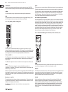
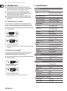
4.8 Aux returns
AUX RETURN
The stereo AUX inputs 1 und 2 let you connect the mixer to additional equipment
(players,eectsprocessors, submixers, etc.). Thesignal is sent to the signal sum.
FX RETURN
The stereo FX RETURN connectors 1 and 2 are linked to the outputs of external
eects processors. Depending on the routing, the signals are sent to the
subgroup or the main mix bus.
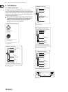
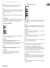
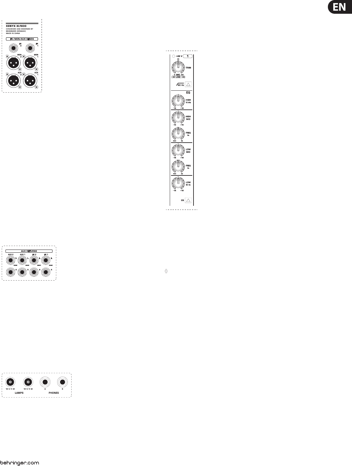
4.9 Light and headphone connectors
LAMPS
The LAMPS plugs are for connecting gooseneck lamps with BNC connectors.
Thepower supply is 12 V _ and the total connection load is 5 Watts a lamp.
PHONES
The PHONES outputs (¼" stereo jacks) let you plug in your headphones.
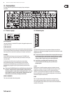
5. Control Elements
This chapter describes the various control elements of your mixing console.
Eachcontrol and switch is explained in full detail.
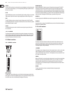
5.1 Mono channels
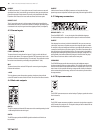
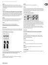
+48 V
This control LED lights up as long as the phantom power is switched on.
Theswitch is found on the rear panel of the unit.
Trim
The TRIM control adjusts the input gain.
◊ Be sure to set this control fully counter-clockwise before you connect or
disconnect a signal source to or from one of the inputs.
The dial oers 2 dierent value ranges. The rst value range between 0 and +60
refers to the microphone input, indicatingthe degree of amplication applied to
the input's signal. Thesecond value range between -20 and +40 dB refers to the
amplication of the line input. When centered (at12o'clock), the line signals are
neither boosted nor cut.
80 Hz
Press the 80 Hz switch to activate the high-pass lter which blends out
low-frequency noise (-3 dB at 80 Hz, 18 dB/octave).
Equalization
The mono input channels provide 4-band equalization with 2semi-parametric
mids. You can boost or cut the bands up to 15 dB. When in center position (0 dB),
the equalizer has a atresponse.
HIGH
The high-frequency range is processed with a shelving lter above 12 kHz.
HIGH MID
A semi-parametric peak lter processes the upper mid range between 400 Hz
and 8 kHz. The FRE control selects the frequency which is boosted or cut by using
the HIGH MID control.