


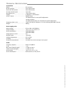
XLR-plug (1)
Line-output. . . . . . . . . . . . . . . . . . . . . . . . Pin 2+, 3- and 1 screen, balanced, floating, 1.55 V (+6 dBm)
Microphone Line 1 (2)
AF-input . . . . . . . . . . . . . . . . . . . . . . . . . . 0 Ohm master, pin 7+, 6- and 14 screen, balanced, floating, adjustable -40 dB
AF-output . . . . . . . . . . . . . . . . . . . . . . . . . 1.55 V (+6 dBm), Pin 5+, 4- and 12 screen, balanced, floating, adjustable -40 dB
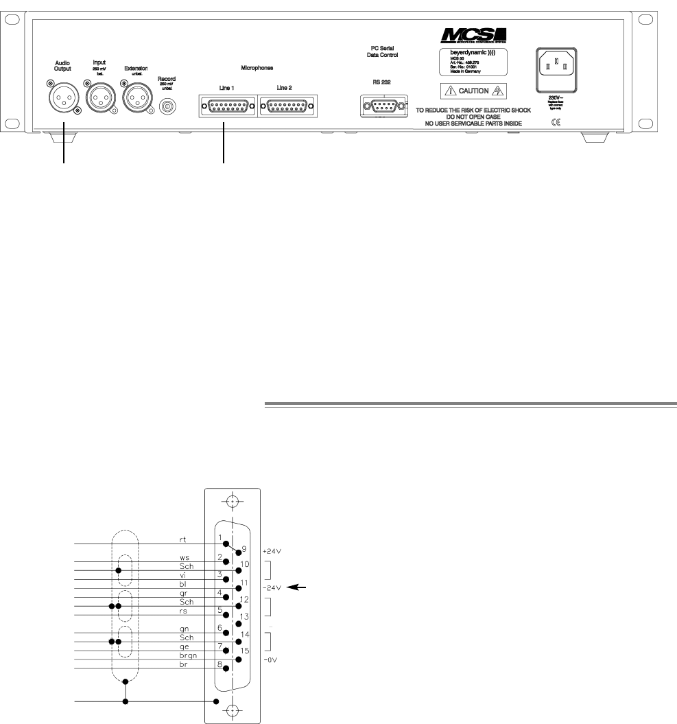
Power supply output . . . . . . . . . . . . . . . . Pin 1 and 9 +24 V, 6 A
Data-Bus-line (CPU) . . . . . . . . . . . . . . . . . Pin 2 = A, Pin 3 = B, Pin 10 = screen
Max. cable length . . . . . . . . . . . . . . . . . . 300 m
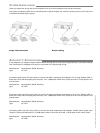
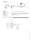
MCS 50 Rear View
Sub-D-plug
Shield CPU
Shield AF Input
AF Output
rt = red
ws = white
Sch = black
vi = purple
bl = blue
gr = grey
rs = pink
gn = green
ge = yellow
brgn= brown/green
br = brown
(1) (2)
C
ONNECTION
S
YSTEM
C
ABLE
only when connected to MCS 100
Non-contractual illustrations. Subject to change without notice. E2/ MCS 50 (11.07)