


Bosch Security Systems | 2007-12 | PLE-1MA030-US, PLE-1MA060-US, PLE-1MA120-US en
Plena Mixer Amplifier | Installation and User Instructions | Description en | 11
2.4 Controls, connectors and
indicators
2.4.1 Front panel
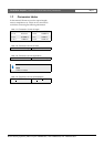
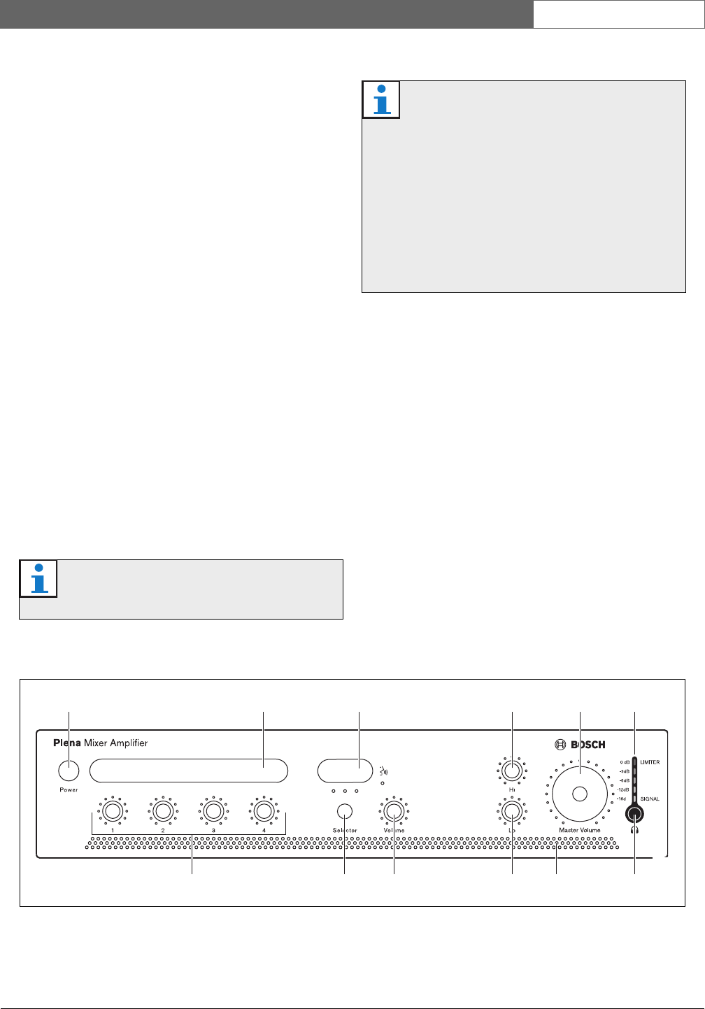
See figure 2.2 for an overview of the controls and
indicators.
1 Power button.
2 Label holder for user-defined description of
microphone/line inputs - custom labels can be
created by user.
3 Label holder for user-defined description of music
sources - custom labels can be created by user.
4 Master high tone control.
5 Master volume control - controls all inputs except
emergency and call station.
6 Output level meter (-18 db, 0 db)
7 Input level control:
• microphone/line 1
• microphone/line 2
• microphone/line 3
• microphone/line 4
8 Music source selector (for music inputs 1, 2, and 3).
9 Music source volume control.
10 Master low tone control.
11 Air inlet holes.
12 Headphone socket.
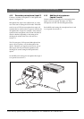
2.4.2 Plena PLE-WP2Z3S wall panel
The optional Plena PLE-WP2Z3S wall panel can be
used to remotely control the unit from a maximum of
four remote locations. The appearance of the wall panel
is matched to the Bosch loudspeaker volume controls.
The music source can be easily changed. The status of
each music source is indicated by an LED.
A standard CAT 5 cable is used to connect the wall
panel to the mixer-amplifier. The maximum distance is
200 m. Please refer to the relevant datasheet for more
information.
Note
Do not obstruct the airflow into the unit.
Note
Users can create custom labels for the
microphone/line inputs and description of the
music sources. These labels can be attached to
the mixer amplifier at position numbers 2 and 3
(see figure 2.2). Colored pins can also be
inserted at various positions around the dial
controls to indicate the favorite settings for a
particular application. For more information on
inserting and removing pins, see section 4.3.2.
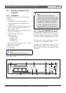
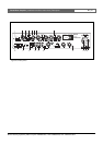
figure 2.2: Front panel
B
7 8 9 10 1211
1
2 3
4 5 6