


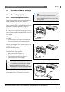

Bosch Security Systems | 2007-11 | PLE-1MA030-EU, PLE-1MA060-EU, PLE-1MA120-EU en
Plena Mixer Amplifier | Installation and User Instructions | Description en | 10
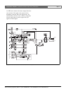
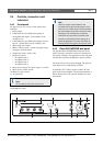
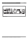
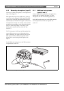
2.4.3 Rear panel
See figure 2.3 for an overview of the connectors and
switches:
1 Tel. emergency/100V input, Euro style pluggable
screw terminal connector - VOX function. This input
has highest priority.
2 Telephone emergency/100V input volume control -
control range -25 dB to 0dB (see number 1).
3 Remote control wall-panel-input, RJ-45 connector.
Wall panel incorporates: BGM source selection, and
zone on/off control.
4 Ducking level control for microphone/line inputs 1
and 2.
5 Music input (number 1 disc), 2x RCA/cinch
connectors. Stereo, summed mono.
6 Music input (number 2 radio), 2x RCA/cinch
connectors. Stereo, summed mono.
7 Music input (number 3 auxiliary), 2x RCA/cinch
connectors. Stereo, summed mono.
8 Music master output, XLR connector - switch setting
for line out, or music only. This output can carry out
either music only, or the master output. For more
information, see chapter 4.2.3.
9 Cooling fan (PLE-1MA120 only).
10 Microphone/line 1 input with trigger, Euro style
pluggable screw terminal connector - DIP switch
settings for: chime, PTT (push to talk), mic/line,
speech filter, and phantom power (see number 12).
Input is wired in parallel with microphone/line 1,
XLR connector (see number 11).
11 Microphone/line 1 input, XLR connector - DIP
switch settings for: chime, PTT (push to talk), mic/
line, speech filter, and phantom power (see number
12). Input is wired in parallel with microphone/
line 1, Euro style pluggable screw terminal connector
(see number 10).
12 DIP switch for microphone/line 1 and microphone/
line 2 (see numbers 10 and 11, and 13 respectively).
13 Microphone/line 2 input, XLR connector - DIP
switch settings for speech filter, mic/line, VOX, and
phantom power (see number 12).
14 Microphone/line 3 input, XLR connector - DIP
switch settings for mic/line, and phantom power (see
number 15).
15 DIP switch for microphone/line 3 and microphone/
line 4 (see numbers 14 and 16 respectively).
16 Microphone/line 4 input, XLR connector - DIP
switch settings for mic/line, and phantom power
(see number 15).
17 Outputs:
• Call only, screw terminal connector 100 V.
• Screw terminal connector 100 V, and 8 Ohm.
18 Mains fuse.
19 Earth connection screw.
20 Mains connector (3-pole).
Note
Always allow adequate space at the rear of the
unit for ventilation.
Note
The unit must be earthed.