


Installation - Wiring
7
Installation - Wiring
Amplifier Fuses
Although the amplifier has an internal fuse, additional fuse protection should be installed as close as possible
to the battery on the positive (+) power wire going to the amplifier. An inline fuse should be installed at no
more than 18" (46cm) on the positive (+) power wire. The rating of the inline fuse should equal the value of
t
he internal fuse of the amplifier if only the single amplifier is connected to this wire. If other devices are con-
nected to this wire, the fuse value should be of sufficient capacity to handle the demand.
Wire Gauge
The amplifier accepts up to 4-gauge stripped wire at the DC power and ground input terminals, and 4-gauge is
recommended. Wire runs should be kept to the minimum practical length.
Power 12v and Ground (GND) Connection
Strip approximately
5
⁄8" (16mm) of insulation. The positive (+) power wire is installed into the amplifier terminal
marked “12v”. The negative (–) wire is installed into the terminal marked “GND”. The ground wire should be
as short as possible and connected directly to the chassis of the vehicle. Make sure that the chassis
connection point is free of rust, grease, dirt, paint, and other materials that may insulate the ground wire from
making proper connection. Tighten the 12v and GND terminals with the supplied 3mm hex wrench to secure
the wire into the terminals. If the power wire must be routed through a drilled or existing hole, use a nylon
panel grommet to prevent the insulation from fraying. Failure to do so could lead to an electrical short if the
wire insulation is worn through and the power wire is shorted to ground.
Remote Input Connection
Use the supplied FEMALE quick-connect terminal to connect the REMOTE trigger lead from the head unit to
the amplifier. Crimp connector to wire from head unit that controls remote turn-on (refer to head unit owner’s
manual). Once the quick-connect terminal is crimped into place, carefully push connector onto recessed MALE
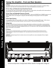
REMOTE terminal adjacent to the RCA input pair (refer to the diagram on page 4).
Speaker Output Connection
Prepare each wire by stripping approximately
5
⁄8" (16mm) of insulation. The positive (+) speaker wires are
installed into the amplifier terminals marked “SPEAKER OUTPUT” / “+” (refer to the diagram on page 4). The
negative (–) speaker wires are installed into the amplifier terminals marked “SPEAKER OUTPUT” / “-”. Tighten
the “SPEAKER OUTPUT”, “+”, and “-” terminals with the supplied 2mm hex wrench to secure the wires into
the terminals. If the speaker wires must be routed through a drilled or existing hole, use a nylon panel
grommet to prevent fraying the wire insulation. Failure to do so could lead to an electrical short if the wire
insulation is worn through and the speaker wires are shorted to ground.
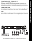
Mono Subwoofer Operation
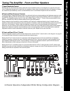
Refer to the diagram on page 4.
WARNING! Subwoofer impedance must not fall below 2 ohms when in MONO mode.