


350Aazur
5
Right Left Right Left
BA
RightLeftRightLeft
BA
Rec Out Tape InAuxBD / DVDTun er / D ABCDMP3
Rec OutTape In Aux BD / DVD Tuner / DAB CD MP3
Right
Left
Right
Left
Loudspeaker Terminals
Power AC
Rated Power Consumption: 230W
Designed and engineered in London, England
azur 350A Integrated Amplifier
www.cambridge-audio.com
Mains Voltage
Selector Switch:
115V/220-230V
AC~50/60Hz
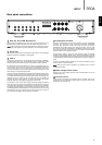
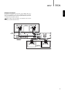
Rear panel connections
MP3, CD, Tuner/DAB, BD/DVD, Aux
These inputs are suitable for any 'line level' source equipment such as
BD/DVD players, DAB or FM/AM tuners, CD players, MP3 players, etc.
Note: These inputs are for analogue audio signals only. They should not be
connected to the digital output of a CD player or any other digital device.
Record Out
These output sockets can be connected to a tape deck or to the analogue
Record In sockets on a MiniDisc or CD recorder.
Tape In
Connect to a tape deck or to the analogue output sockets on a MiniDisc,
portable digital music player or CD recorder using an interconnect cable
from the recorder's Line Out sockets to the amplifier's Tape In sockets.
The Tape Input circuit of the 350A is a ‘monitor’ type, different from the
other six inputs. For the six normal inputs, the source selected for listening
to will also be sent out of the Rec outputs for recording. The source
currently being listened to and (optionally) recorded is then shown on the
front panel by a corresponding blue LED.
However, when the Tape Mon Input is selected, the Tape Mon LED will also
illuminate, indicating that the Tape Monitor Input is now being listened to
with a different source being sent out of the Rec outputs for recording. The
recording source is shown by the first LED and can be changed by
pressing the other source buttons. To switch Tape Monitor off, simply
press the Tape Mon button again, toggling this function off.
This feature is most useful when using three-head analogue cassette
decks which allow the signal being recorded to be played back live off tape
(via a third head) whilst it is simultaneously recorded. It is then possible,
by toggling the Tape Monitor input on and off, to compare directly in real
time the original and recorded signal so that adjustments to the recording
parameters of the tape machine can be made. (Consult the manual of
your three-head analogue cassette deck for full details).
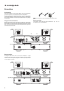
Loudspeaker terminals
Two sets of loudspeaker terminals are available, A (main loudspeaker
terminals, left terminals) and B (secondary switchable loudspeaker
terminals, right terminals). Connect the wires from your left channel
loudspeaker to the LEFT positive and negative terminals, and the wires
from the right channel loudspeaker to the RIGHT positive and negative
terminals. In each case, the red terminals are the positive outputs and the
black terminals are the negative outputs.
Care should be taken to ensure no stray strands of wire are shorting
speaker outputs together. Please ensure that the loudspeaker terminals
have been tightened adequately to provide a good electrical connection. It
is possible for the sound quality to be affected if the screw terminals are
loose.
The use of A and B speakers affords you an easy and inexpensive way to
create a simple multi-room system.
Note: When using two pairs of speakers, use speakers with a nominal
impedance of 8ohms.
Mains voltage selector switch
Switches the mains voltage between 115V and 220-230V. For use by
installer/dealer only.
AC power socket
Once you have completed all connections to the amplifier, plug the AC
power cable into an appropriate mains socket and turn the unit on. Your
amplifier is now ready for use.
1
1
2
3
4
5
6
ENGLISH
2 3 4
5
6