


English
Assembling the Stand
E-31
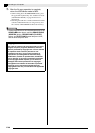
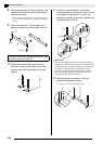
13.
Secure the corner brackets to the stand using
the screws you removed in step 10.
IMPORTANT!
• Press down on the edges of the pedal unit as you
tighten the corner bracket screws.
• The side panels have joint connectors inside that
engage with the corner bracket screws. If you have
trouble inserting the screws into the joint connector
screw holes, use a screwdriver to rotate the joint
connector and adjust the position of the screw hole
for easier access. See the detail drawing (marked
with a star) in the above illustration.
To tighten the joint connector and screw
14.
Connect the pedal unit cable.
• For details about connections, see “To connect the
cable” (page E-32).
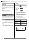
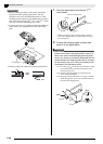
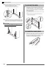
• Perform steps 1 through 9 starting on page E-28.
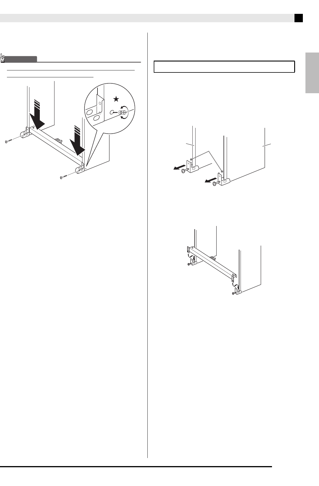
10.
Loosen the bracket screws at the bottom of
the stand’s side panels
and to create a
gap between the side panels and corner
brackets as shown in the illustration.
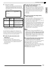
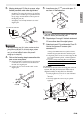
11.
As shown in the illustration, insert the pedal
unit brackets into to the gaps you created in
step 10.
(1) Rotate the screw counterclockwise about three
turns to ensure that the screw is in the center of the
joint connector.
(2) Slowly rotate the screw clockwise and confirm that
it tightens without resistance. If you feel any
resistance, it means that the screw is not engaging
properly with the joint connector. Rotate the screw
counterclockwise again and try to get it to engage
properly.
(3) If you experience problems getting the screw to
engage properly, use a screwdriver to rotate the
joint connector 180 degrees. Next perform steps (1)
and (2) again to engage the screw from the screw
hole on the other side.
• Forcibly tightening a screw while it is not
engaged properly can strip the threads of the
screw and joint connector, making it impossible
to tighten the screw.
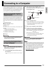
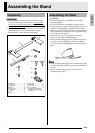
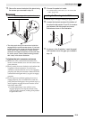
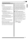
Locating the Stand against a Wall
B
A
Gap