CA30D Acoustic Amplifier
4
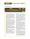
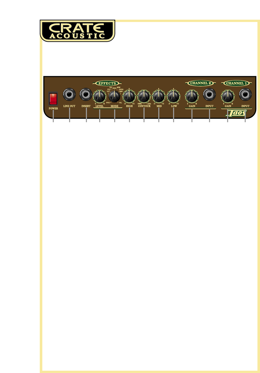
The Front Panel:
1: Power. Use this switch to apply power to
the amplifier: the amp is on when the top
of the switch is depressed, off when the
bottom of the switch is depressed. The
switch illuminates when the amp is on.
2: Line Out. Use this jack to connect a high
impedance, unbalanced line level signal
to a house sound board, a recording con-
sole or another amplifier.
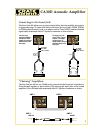
3: Insert. Use this jack to add external effects
to the signal. The ring = send (line out),
tip = return (line in), sleeve = ground.
This jack can also be used to “chain” mul-
tiple amplifiers together, since connecting
to this jack does not interrupt the signal
going to the amplifier. (See the illustra-
tions on page 5 for more information.)
4: Effects Level. Use this control to adjust
the amount of digital signal processing
applied to the output signal.
5: Effects Mode. Use this control to select the
type of digital signal processing applied to
the output signal. (See the section entitled
“The DSP Section” on page 6 for more infor-
mation.)
6: High. This serves as the treble control for
both channels. Adjust this control so your
high notes and harmonic overtones are
lively but not overpowering.
7: Contour. Use this control to set the center
point of the mid control. This control
should be set at the frequency which
gives you the most natural midrange
tones.
8: Mid. This serves as the midrange control
for both channels. Adjust this control to
get the best projection and midrange
tones for your instrument. The center
point of the mid control is chosen by the
setting of the contour control (#7).
9: Low. This serves as the bass control for
both channels. Adjust this control to get
the best sounding bass response for your
instrument. Excessive boost of the low
control can cause an unnatural howling
(acoustic feedback from your instrument)
and should be avoided.
11,13:
Input 2, Input 1. The signal output from
your acoustic instrument, tape player,
rhythm machine, high-Z microphone or
other source may be connected to either or
both of these jacks by means of a shielded
signal cable. Each of the input jacks is gov-
erned by its corresponding gain control
(#10 for Input 2, #12 for Input 1). The sig-
nals from these two jacks are summed
together after their gain stages.
10,12:
Gain 2, Gain 1. Use these controls to set
the input gain level for the corresponding
input jack. These controls set the level of
the input signal and serve as the amplifi-
er’s volume controls.
14: AC Line Cord. (Rear panel, not shown)
The grounded power cord should only be
plugged into a grounded power outlet
that meets all applicable electrical codes
and is compatible with the voltage,
power, and frequency requirements stat-
ed on the rear panel. Do not attempt to
defeat the safety ground connection.
1 2 3 6 7 8 94 5 10 11 12 13


