


4
GFX2200HT GUITAR AMPLIFIER
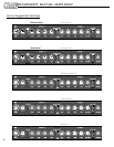
. POWER: Use this switch to turn the ampli-
er on (top of the switch depressed) and off
bottom of the switch depressed).
. ON LED: This LED illuminates when the
mplifier is turned on.
. CHANNEL SELECT FOOTSWITCH: In-
ert the 1/4” stereo plug on the cable attached
o the two-button footswitch (supplied) into
his jack. This will allow you to use the
ootswitch to control channel and gain selec-
on (Channel A - see #18).
. DSP FOOTSWITCH: Insert the 1/4” mono
lug on the cable attached to the two-button
ootswitch (supplied) into this jack. This will
llow you to use the footswitch for on/off con-
rol of the selected DSP effect.
. DSP MODE: Use this control to select one
f the 16 built-in digital effects. A listing of the
ffects is shown on page 3.
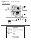
. DSP LEVEL: Use this control to adjust the
mount of the digital effect. In its fully counter
lockwise position the signal will be “dry”
without any effect). As you rotate the control
lockwise the amount of effect increases.
CHANNEL B: The Clean Channel:
. BRIGHT: This switch, when depressed,
oosts the upper frequencies of Channel B.
. LEVEL: Use this control to adjust the out-
ut level of Channel B.
. HIGH: Use this control to adjust the high
requency level of Channel B.
10. MID: Use this control to adjust the
midrange frequency level of Channel B.
11. LOW: Use this control to adjust the low
frequency level of Channel B.
12. CHANNEL SELECT: Use this switch to
select either channel. With the switch in the
out position, Channel B is selected and the
adjacent LED illuminates. When the switch is
depressed, Channel A is selected.
CHANNEL A: The Overdrive Channel:
13. LEVEL: Use this control to adjust the out-
put level of Channel A.
14. HIGH: Use this control to adjust the high
frequency level of Channel A.
15. MID: Use this control to adjust the
midrange frequency level of Channel A.
16. LOW: Use this control to adjust the low
frequency level of Channel A.
17. GAIN TWO: Use this control to adjust the
amount of heavy distortion for Channel A.
Gain Two produces more intense distortion
than Gain One (#19) and is active when the
Gain switch (#18) is depressed.
18. GAIN SELECT: Use this switch to select
one of the two gain controls for Channel A
(#17, #19). When the switch is depressed,
gain two is selected and gain one is disabled.
Both of the adjacent LEDs will illuminate. With
the switch in the out position, gain one is
selected. The right-side LED will illuminate.
When a footswitch (#3) is used, this switch is
disabled. The LEDs continue to function in the
manner described.
19. GAIN ONE: Use this control to adjust the
amount of light distortion for Channel A. Gain
One produces less intense distortion than
Gain Two (#17) and is active when the Gain
switch (#18) is in the out position.
20. INPUT: Use this 1/4” jack to connect your
guitar to the amplifier by means of a shielded
instrument cable.
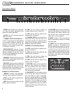
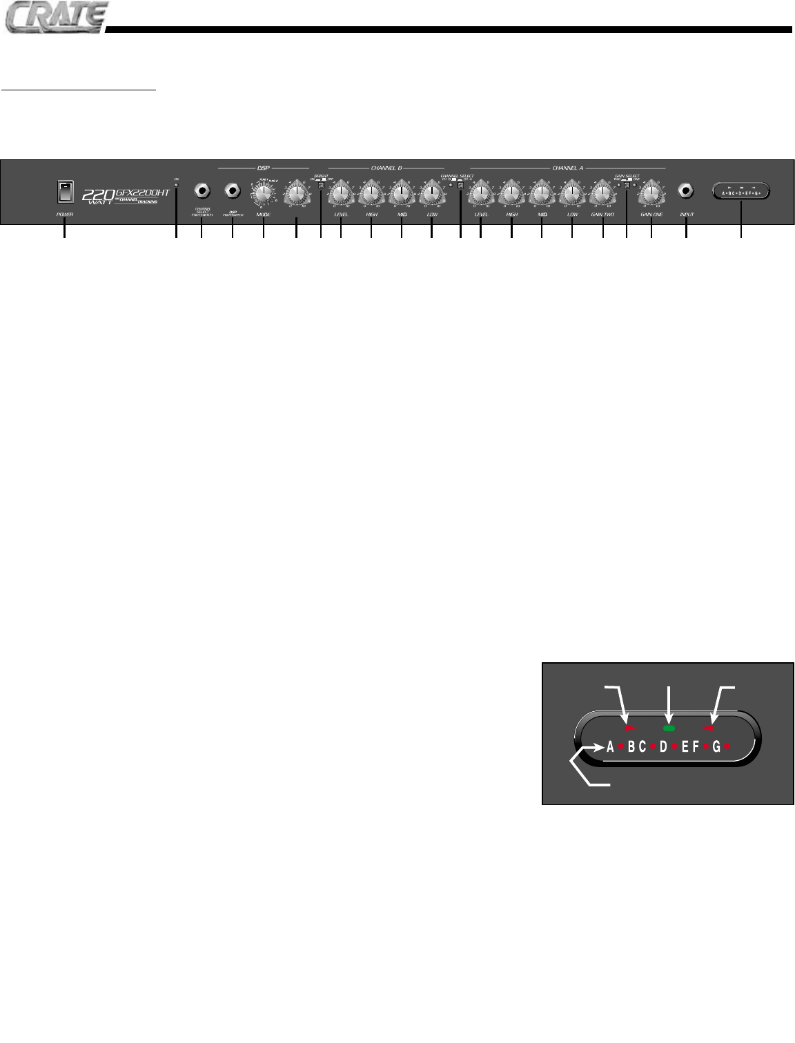
21. TUNER: The tuner is active whenever the
amplifier is turned on. The bottom row of
LEDs correspond to the strings of your guitar.
The top row of LEDs indicate which way you
need to adjust each string for proper tuning. A
string is properly tuned whenever the corre-
sponding LED on the bottom row and the LED
in the center of the top row are illuminated.
(See detail below.)
The Front Panel:
RTRY
RTRY
T-WAH
T-WAH
I-WAH
I-WAH
REV
REV
CHO 1
CHO 1
CHO 2
CHO 2
LY
LY
BLR
BLR
OCTV
OCTV
N
N
LEVEL
1 2 3 4 5 6 7 8 9 10 11 12 13 14 15 16 17 18 19 20 21
"FLAT"
"TUNED"
"SHARP"
STRING INDICATORS