


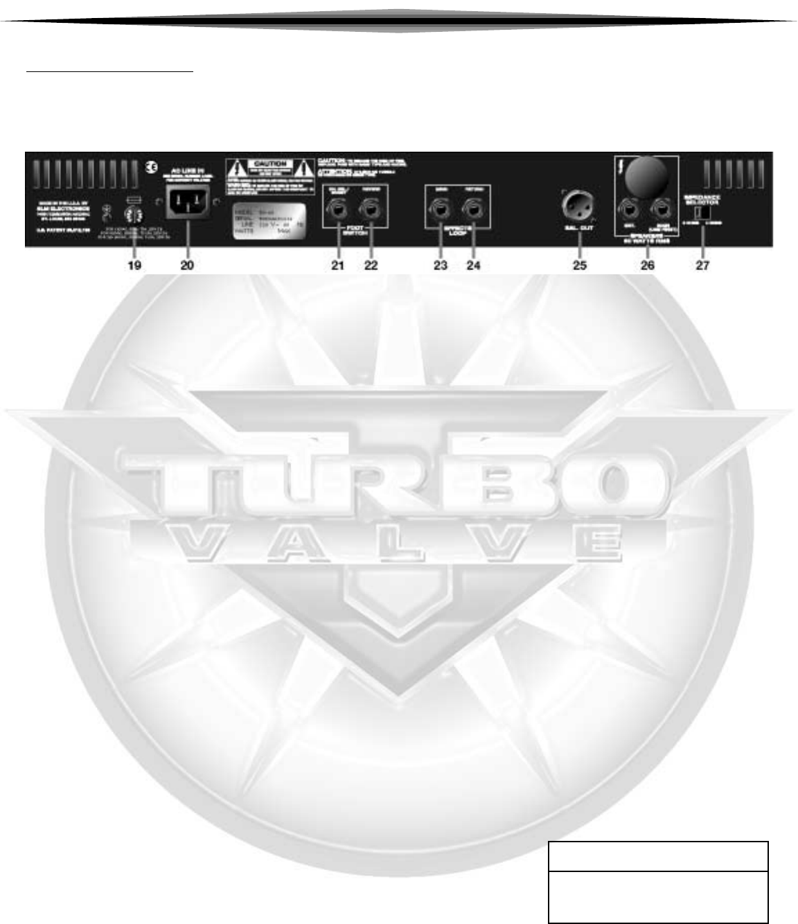
THE REAR
PANEL:
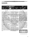
19. FUSE: This fuse protects the
amplifier against damages caused by
overload conditions in the unit. If the
fuse blows, replace it only with the
same size and type as indicated on the
rear panel. If the fuse blows continual-
ly, the line voltage may be incorrect, or
the amp may need servicing.
20. AC LINE IN: Firmly plug the
female end of the supplied power cord
into this socket, pushing it in until it is
fully seated. Plug the male end of the
cord into a properly grounded AC out-
let of the correct voltage. DO NOT
DEFEAT THE GROUND PIN OF THE
AC PLUG! Use only the supplied
power cord. If the amplifier is to be
used outside of the United States, see
your authorized Crate dealer for infor-
mation about alternate line cords and
power converters if needed.
21. CHANNEL SELECT/BOOST
FOOTSWITCH JACK: Connect a
stereo 1/4" plug (tip/ring/sleeve) here
from either a two or three button
footswitch (such as the Crate CFP-2 or
CFP-3) for control of channel switch-
ing. The tip of the jack is for channel
switching; the ring is for boost control.
When a footswitch is connected here,
the front panel channel select and
boost switches (#7 and #9) are dis-
abled.
22. REVERB FOOTSWITCH JACK:
Connect a mono 1/4” plug (tip/sleeve)
here from either a one or three button
footswitch for reverb on/off control.
23. EFFECTS LOOP SEND: When
using an external effects device, use
this jack to send the signal from your
amp to the effect. Connect a shielded
instrument patch cord from the send
jack to the input jack of the effect.
The send jack also doubles as a
"preamp out" jack, to feed a post-eq
signal to a mixing board, recording
console or external amplifier.
24. EFFECTS LOOP RETURN: Use
this jack to return the signal from an
external effects device back to your
amplifier. Connect a shielded instru-
ment patch cord from the output jack
of the effect to the return jack.
The return jack also doubles as a
"power amp in" jack, to feed a line-
level signal directly into the internal
power amp. This is useful when "slav-
ing" two amplifiers together.
25. BALANCED OUT JACK: This XLR
connector supplies a balanced output
signal from the power amp for patching
into a mixing board, recording console
or external amplifier. The signal is elec-
tronically compensated to simulate the
sound of a "miked" cabinet.
26. SPEAKER JACKS: Use these
jacks to connect the amplifier to your
speaker cabinet(s). Use the “Main” jack
first; never use the “Ext” jack if nothing
is connected to the “Main” jack!
Always keep the impedance at 4 or 8
ohms, with the Impedance Selector
switch (#27) at the proper setting.
IMPORTANT NOTE ABOUT CERTAIN
EXPORT UNITS: In some areas 1/4”
jacks are not acceptable for use on
amplifiers capable of high output power
levels. For this reason the 1/4” speaker
jacks on your amplifier may be factory
sealed. In this case, use the Speakon
®
jack to connect the amplifier to your
speaker cabinet(s) using cables rated
for high power, terminated with the
appropriate connectors.
27. IMPEDANCE SELECTOR: For the
best performance and least strain on
your amplifier, you MUST properly
match the impedance of your amplifier
to that of your speaker cabinet(s). Set
the selector switch to the 4 or 8 ohm
position, depending on the total
impedance of your speaker cabinet(s).
The chart below can help you deter-
mine that impedance based on the fol-
lowing combinations of speakers con-
nected in parallel.
CABINET NUMBER OF TOTAL
IMPEDANCE CABINETS IMPEDANCE
8 OHMS 2 4 OHMS
16 OHMS 2 8 OHMS
16 OHMS 4 4 OHMS
Speakon
®
is a registered trademark of Neutrik USA
5
TTVV--6600//112200//66221100//66221122 GGUUIITTAARR AAMMPPLLIIFFIIEERRSS