


Crown International
1718 W. Mishawaka Rd.
Elkhart, IN 46517-9439
TEL: 574-294-8000
FAX: 574-294-8FAX
www.crownaudio.com
©
2005 Crown Audio
®
Inc. Specifi cations subject to change
without prior notice. Latest information available at www.
crownaudio.com. Mini-Boundary is a trademark, and Crown
and Crown Audio are registered trademarks of Crown
International. Printed in U.S.A.
7/05 103278 -5A
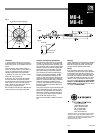
Fig.4
Fig. 3
MB-4
MB-4E
Installation
1. Typical placement for each mic is at arm’s
length from the user. Install one microphone in
front of each person, or one between every two
people.
If the microphone will be used on a lectern,
install it on an open surface. Do not install it in
a cavity or recessed area as the frequency re-
sponse and polar pattern will be degraded.
2. Orient the mic so the word “Crown” is read-
able by the user (right-side-up).
3. MB-4 only: Plug a mic cable with a female
XLR-type connector into the power module.
Connect the other end of the cable to a phantom
power supply. Or if your mixer has phantom
power, connect the mic cable directly to a mic
input and turn on phantom power.
Wire the MB-4E to the MB-100 or MB-200 inter-
face as described in the interface data sheet.
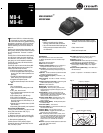
Fig.5
Horizontal-Plane Polar Response
Architects’ and Engineers’ Specifi cations
The microphone shall be the Crown model MB-
4, MB-4E, or equivalent. The microphone shall
be a half-supercardioid electret condenser type.
The microphone shall use the principle of phase
coherency achieved by mounting a small-diam-
eter element very near a boundary. This elimi-
nates comb fi ltering in the audible spectrum.
The microphone will exhibit excellent off-axis
response and gain-before-feedback. The MB-
4 shall have a permanently attached 15-foot
(4.572-m) cable connected to an XLR-type con-
nector with built-in mic electronics. Powering
shall be by 12-48V phantom power. The MB-4E
shall have a permanently attached 15-foot
(4.572-m) cable without electronics/connector.
Its powering shall be by the Crown MB-100 or
MB-200 Interface.
At the output connector, nominal sensitivity shall
be 22 mV/Pa. Maximum SPL shall be 120 dB
SPL for 3% THD. Equivalent noise shall be 22
dBA nominal. Frequency response shall be 50
Hz to 15 kHz with a uniform off-axis response,
about 20 dB down at the rear nulls.
The Crown models MB-4 and MB-4E are speci-
fi e d .
Warranty
Crown professional microphones are guaranteed
against malfunction for a period of three years
from date of original purchase. See enclosed
warranty sheet for additional information.
Service
If the microphone does not function properly,
check that it is aimed correctly and is connected
as described in this data sheet. If there is hum
or no signal, fi rst repair or replace the cable. For
the MB-4E only, check the slide-switch setting
in the MB-100 or MB-200 Interface. If the mic is
defective, return the microphone and the inter-
face in their original packaging to Crown Factory
Service, 1718 West Mishawaka Road, Elkhart,
IN 46517-9439. For further assistance or techni-
cal support call 800-342-6939.
FRONT
REAR
0˚
30˚
60˚
90˚
120
˚
150˚
180˚
210˚
240˚
270˚
300˚
330˚
–20
–15
–10
–5
–0
1 kHz
5 kHz
200 Hz
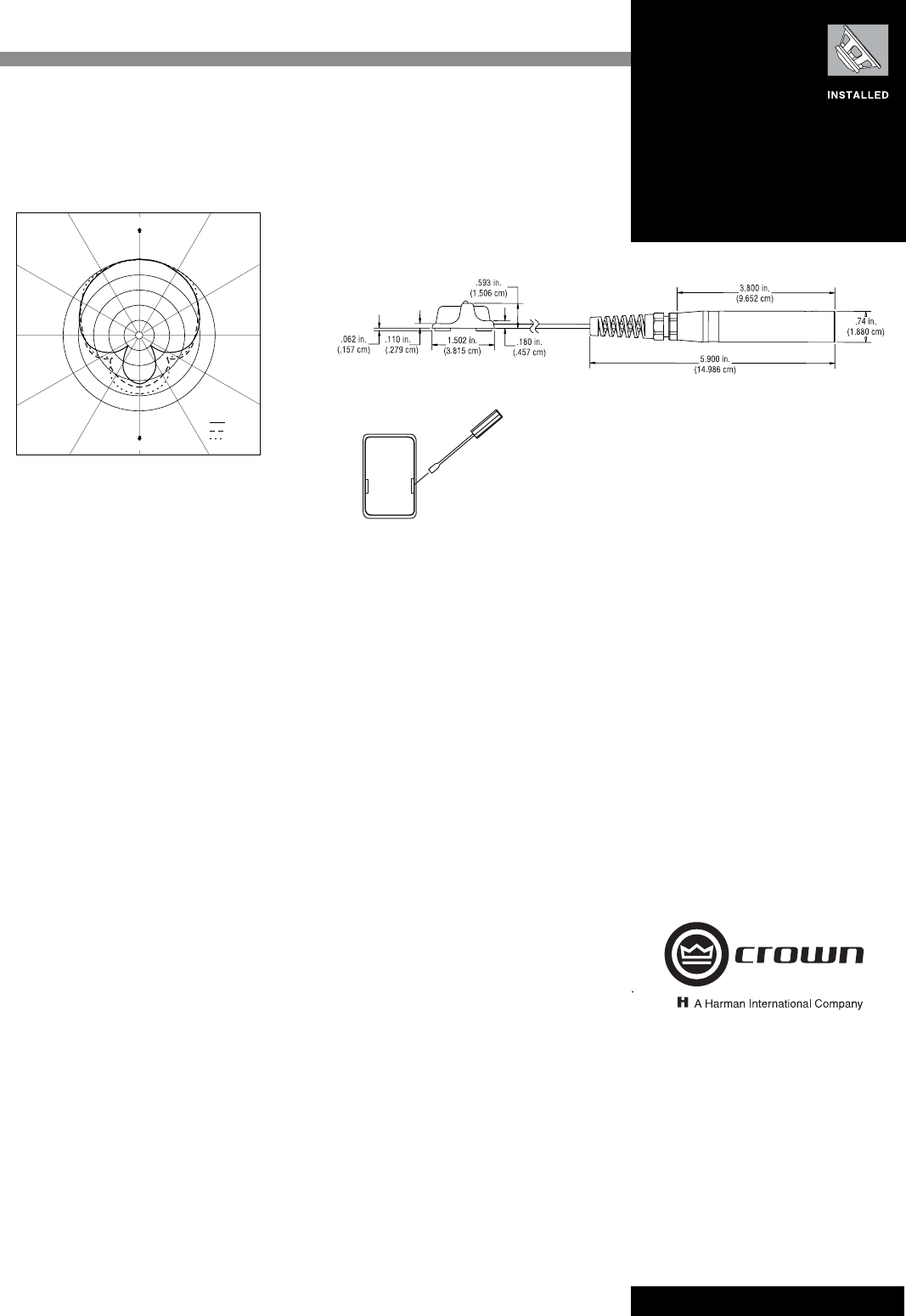
BOTTOM VIEW
SCREWDRIVER
PRY OPEN HERE AND
ON OPPOSITE SIDE