


Crown International, Inc.
1718 W. Mishawaka Rd.
Elkhart, IN 46517-9439
TEL: 574-294-8000
FAX: 574-294-8FAX
www.crownaudio.com
serves as a cough button or privacy button.
After choosing the option you prefer, set the
DIP switches according to the label on the
bottom of the microphone (see Fig. 5). The LED
in the microphone housing will light when the
mic is on.
If you want the mic to be continuously on (so
you can gate it on and off externally), set the
DIP switch to “DISABLE MIC GATING.”
Installation
Typical placement for each microphone is at
arm’s length from the user. Either place one
microphone in front of each person or one
between every two people. The front of the
microphone is indicated by an arrow on the
bottom of the base plate.
If the microphone is used on a lectern, place it
on an open surface, not in a cavity. Otherwise
the frequency response and polar pattern will
be degraded.
Solder the shield, green and white leads to an
XLR type connector, shield to pin 1, green to 2,
white to 3. Plug this connector into the input of
a phantom-power supply such as a Crown PH-
1A. Connect the output to a mixer mic input.
Or if your mixer has phantom power built in,
connect each mic cable directly to a mixer mic
input.
PCC-170SWO
Specifi cations subject to change without prior
notice. Latest information available at www.crown-
audio.com. Crown, Crown Audio, PCC
and Phase
Coherent Cardioid are registered trademarks of
Crown International, Inc.
©
2006 Crown Audio
®
, Inc.
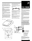
Sample circuit for remote sensing.
10/06
101793-8
3.4"
8.6 cm
.900"
2.3 c
m
4.84"
12.3 cm
TOUCH
Fig. 6
Fig. 4 Dimensions
Fig. 5
Fig. 7
Dimensions are to outside of plastic housing
The PCC includes two keyhole slots in its base
to accept mounting screws. To screw the PCC
to a table top, follow this procedure:
1. Punch out the keyholes marked on the label
underneath the base plate (use a razor blade,
small screwdriver, etc.).
2. Using the template (Fig. 6), mark the loca-
tion of two holes in the table where you want to
mount the mic. These holes are 1.6-inch (4.064
cm) apart, center-to-center.
3. Screw two #8 woodscrews (.270” dia. head)
into the table at the locations you marked.
4. Loosen the screws enough to receive the mic
and to hold it with a friction fi t.
Operation
Press near the center of the switch. The micro-
phone will switch on or off according to how
you set the DIP switches. When the mic is on,
the LED in the housing is lit.
If you set the DIP switch to “DISABLE MIC
GATING,” the mic is always on. Pressing the
switch will light the LED and activate remote
sensing.
The contact-closure leads (red and black) pro-
vide remote sensing of mic attenuation. Switch
closed (low resistance) is mic ON. Switch open
(high resistance) is mic OFF.
To detect when the mic is on, apply a small
voltage to the remote sensing leads (Fig. 7).
Apply +DC to the red lead and -DC to the black
lead. Large voltage and current may induce
noise into the audio output. Maximum switch
voltage and current are 350 V, 200 mA. On-
resistance is 7 to 10 ohms with the included
15-foot cable.
Warranty
Crown professional microphones are guaran-
teed against malfunction for a period of three
years from date of original purchase. Please
refer to the enclosed full warranty sheet for
more detail.
Service
If the microphone does not function properly,
replace or repair mic cables and connectors,
check the power supply. If service is required,
return the microphone in its original packag-
ing to: Crown Factory Service, 1718 W.
Mishawaka Road, Elkhart, IN 46517-9439.
A Service Return Authorization (SRA) is re-
quired for product being sent to the factory for
service. An SRA can be completed on line at
www.crownaudio.com/support/factserv.htm.
For further assistance or technical support call
800-342-6939.
MIC
RL 2K
9V
RED 5
+DC
BLK
–DC
AUDIO +
AUDIO –
GRN
WHT
1
4
2
3
SHIELD