10
ENGLISH
6
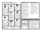
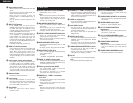
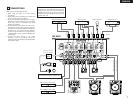
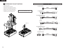
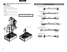
ROTATING INPUT SELECT SWITCHES
1. Disconnect the power.
2. Remove knobs from the top panel.
3. Remove the 6 screws attaching the top panel.
4. Remove the 2 screws attaching the switch unit.
5. Rotate the switch unit to the desired location.
6. Reinstall the 2 screws holding the switch unit.
7. Reinstall the top panel and reattach knobs.
Switch unit
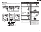
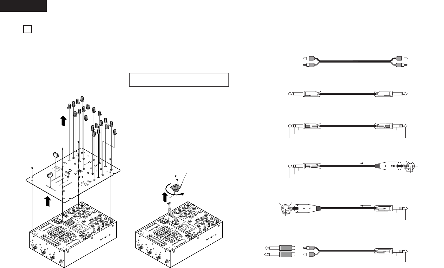
Cable 1
RCA pin plug
Unbalanced (1/4” TS)
Sleeve=GND
Ring=Cold
Tip=Hot
Unbalanced (1/4” TS)
Balanced (1/4” TRS)
Cable 2
Sleeve=GND
Ring=Cold
Tip=Hot
Balanced (1/4” TRS)
Cable 3
Sleeve=GND
Ring=Cold
Tip=Hot
Balanced (1/4” TRS)
Balanced
Cable 4
1=GND
2=Hot
3=Cold
1=GND2=Hot
3=Cold
Sleeve=GND
Ring=Cold
Tip=Hot
Cable 5
About the Cables
Unbalanced
(For SEND/RETURN)
(For BALANCED MASTER OUT)
(For MIC)
(For BALANCED MASTER OUT)
Balanced (1/4” TRS)
XLR3-12C
Balanced
XLR3-11C
Adaptor
Cable 6
Sleeve=GND
Ring=R
Tip=L
Balanced (1/4” TRS)
R=Ring
L=Tip
(For MIC EFFECT LOOP)
NOTE:
• Only the knob for CUE SELECT is different.
(For RCA in/out jack)


