


CH230/CH230W Condenser Cardioid Hanging Microphone
CH230/CH230W Condenser Cardioid Hanging Microphone
2
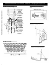
up with “INPUT-OUTPUT” aligned as
shown in Figure 3. Start the assembly by
inserting the two 1
1
/
4
-in. screws into the up-
per left-hand and lower right-hand holes,
drop on the internal toothed lockwashers,
thread on the spacer and tighten against the
plate with a wrench. Repeat the procedure
for the two
3
/
16
-in. screws. Place the fiber
washer on each spacer.
3. Position the printed circuit board with
the larger terminal block and the transformer
over the printed “OUTPUT” label. Align the
screw holes in the upper right and lower left
corners of the printed circuit board with the
two 1
1
/
4
-in. screws and push down until the
board rests against the four fiber washers.
Take the remaining two
3
/
16
-in. screws and
two fiber washers and fasten the board to the
plate.
4. Determine the length of cable required
before attaching the microphone cable to the
printed circuit board. If the cable must be
trimmed, measure the length and add three
inches. Trim the cable by removing about 1
in. of the outside jacket, then separate the
shield from the red and white wires.
Strip
1
/
4
in. of insulation from the red and
white wires. Push the bare wire ends of mi-
crophone cable through the center hole in
the plate and the circuit board, then insert
the wires into the “INPUT” terminal block.
Follow the label instructions printed on the
plate. With the small-blade screwdriver,
tighten the screws in the terminal block.
5. Use the strain relief to fasten the micro-
phone cable to the plate by capturing the
cable about
1
/
2
in. from the front of the plate,
then orient the flats of the strain relief with
the flats of the center hole and squeeze and
push the strain relief into the center hole. The
strain relief will lock into place.
6. To attach the mixer cable to the circuit
board, trim
1
/
4
in. of insulation from the cable
wires and insert the wires into the “OUT-
PUT” terminal block. Follow the label in-
structions and insert the cable shield into
“SHLD GND,” and the remaining wires into
terminals 2 and 3. Warning: the CH230 and
CH230W have terminal 2 positive with a
positive pressure on the diaphragm, so be
aware of possible phasing problems if the
wires for terminals 2 and 3 are reversed.
Tighten the terminal block screws with a
small-blade screwdriver.
7. Set the roll-off switch to the position
desired. The rolloff filter is a two-pole, 12-
dB-per-octave high pass with a corner fre-
quency of 75 Hz.
8. Position the shield box with the slotted
end over the mixer cable and the screw holes
over the two 1
1
/
4
-in. screws. Push down the
shield box over the circuit board until the
shield is sitting on the plate. Inspect the mixer
cable connection for any shorts of terminals
2 or 3 to the shield box. With the wrench,
fasten the shield box to the plate with the
two split-ring washers and the two hex nuts.
9. Gently push the assembly into the
wallbox and fasten the assembly in place
with the two remaining
1
/
2
-in. #8-32 screws.
10. To orient the microphone in the proper
direction, loosen the holding nut on the back
of the microphone and slightly twist the mi-
crophone on the wire holder (clockwise ro-
tation moves the microphone to the left;
counterclockwise rotation moves the micro-
phone to the right). Tighten the holding nut.
Note: for fixed installations, allow the mi-
crophone cable to hang for at least 24 hours
so the cable can completely relax and estab-
lish a set. Bend the hanger wire to position
the microphone in the vertical plane.
Application Notes
When hanging one or more microphones to
provide coverage for a choir, instrumental,
or theater group, the best microphone posi-
tion for optimum sound quality and feedback
control depends on many factors—sound
system characteristics, construction of the
auditorium or theater, and the size and na-
ture of the performing group. Two general
rules to observe for the best sound coverage
are (1) microphone position and (2) the “3-
to-1 rule.”
The first rule is to suspend the microphone
approximately two to three feet in front of
the first row of performers and two to three
feet higher than the heads of the last row of
performers. The microphones are usually
aimed to point at the last row of performers
(Figure 5).
The second rule, the “3-to-1 rule,” should be
applied when more than one microphone is
required, and their outputs are combined (as
with a mixer). Following the 3-to-1 rule
avoids the deep voids and dips in frequency
response that occur when two or more mi-
crophones “see” the same signal from
slightly different distances. The 3-to-1 rule
is as follows: when multiple microphones are
used, place them at least three times as far
apart as any one of them is from the nearest
sound source. Figure 6 shows a proper ap-
plication of the 3-to-1 rule.
The CH230 and CH230W may also be used
to provide coverage for live theater applica-
tions (Figure 7). Most of the action occurs
at center stage, so the microphone should be
positioned above and pointed to the center
of the stage.
Architects' and Engineering
Specifications
The microphone shall be a back-electret con-
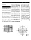
denser type with a frequency response of 30
Hz to 20 kHz. The microphone shall have a
cardioid polar pattern with a rear response
which is typically 20 dB below the front re-
sponse at 1.0 kHz. The microphone shall
have an output power level of –21.7 dB,
where 0 dB = 1 milliwatt per pascal, and
output shall not be appreciably affected by
the following temperature and humidity ex-
tremes: –29° to 74° C (–20° to 165° F) when
relative humidity is 0-50%; –29° to 57° C (–
20° to 135° F) when relative humidity is 0-
95%. The microphone shall have a nominal,
balanced output impedance of 150 ohms
when connected to its electronics module.
The microphone shall have a low-gloss black
finish (CH230) or a low-gloss white finish
(CH230W). The cable color shall match the
transducer. A switchable, two-pole high-pass
filter (f
0
= 75 Hz) shall be provided.
The transducer shall have a wire hanger for
directing the microphone. Dimensions: the
transducer shall be 10.5 mm (0.42 in.) wide
and 41.9 mm (1.65 in.) long; the cable shall
be 9.1 m (30 ft) long and 2.6 mm (0.106 in.)
in diameter. The electronics module shall fit
into either a switch box or four-inch electri-
cal box, with a rectangular switch-box plate
and circular plaster-ring cover provided.