


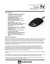
PC Boundary
Switch Setting Guide:
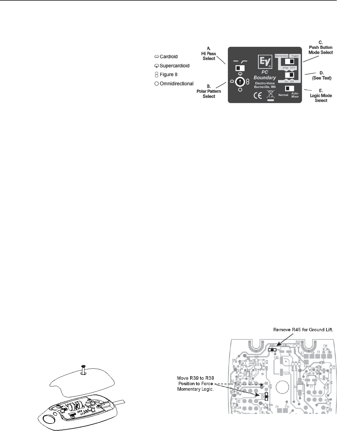
Audio (Switches A & B)
A – Hi Pass Filter
Start with this switch set to the left (flat response). If the mic
is in a location where low frequency rumble or wind noise is
encountered, moving this switch to the right will help by
reducing low frequency sensitivity.
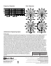
B – Polar Pattern
The cardioid polar pattern works well for most installations. If
feedback from a sound system occurs, switching to the
supercardioid pattern will usually allow increased mic gain
before feedback. The figure 8 pattern can be used to mic two
people sitting on opposite sides of a table, potentially reducing
the total number of mics required. The omnidirectional pattern
is best suited for situations where there is no sound
reinforcement system present, such as for recording.
Mute Switch Configuration (Switches C & D)
(The membrane switch on the top of the PC Boundary microphone.)
Momentary modes:
When switch “C” is set to the left, the mute switch action is momentary. (If switch “D” is in the left hand position, the mic will be in push-to-mute
mode. If switch “D” is in the right hand position, the mic will be in push-to-talk mode.)
Toggle Modes:
When switch “C” is in the right hand position, the mute switch will be in toggle (push-on / push-off) mode. (When the mic is in this mode, the
setting of switch “D” determines if the mic audio should be muted when power is first applied. If switch “D” is in the right hand position, the mic
audio will be muted when power is first applied. If switch “D” is in the left hand position, mic audio will be on when power is first applied.)
Logic Mode Select (Switch E)
When switch “E” is set to the left, the PC Boundary operates as a normal microphone. Mic muting and operation of the LED is controlled by the
pushbutton on the top of the mic.
When switch “E” is set to the right hand position, the mic will be in automatic mixer mode, and the following will apply:
1) Mic audio is always on.
2) The automatic mixer controls LED operation.
Logic Signals
Logic signal cable hookup guide:
Green – Logic Ground
White – Switch Logic
Orange – LED Control
If the PC Boundary mic is in momentary mode (see above section on the mute switch), the logic level on the white wire will normally be “high”, and
go “low” when the mute button is pressed. If the mute switch is set for toggle mode, the logic will toggle from high to low, or from low to high,
each time the button is pressed. (If desired, a pc board change can be done to force the logic to always be momentary, regardless of switch
settings. See diagram.)
LED Control
When the mic is in automatic mixer mode, a low logic signal on the
orange LED control wire will cause the LED to light.
Logic Ground Lift
If necessary, the logic and audio grounds can be separated. This
requires removing a resistor from the pc board. See diagram.
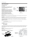
Figure 1:
Mic Switch Interface
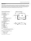
Figure 3:
PCB Jumper Locations
Figure 2:
PCB Access
Remove the center
screw and grille to
access the pc
board.