


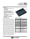
Frequency Response:
12000 Portland Avenue South, Burnsville, MN 55337
Phone:952/884-4051, Fax:952/884-0043
www.electrovoice.com
© Telex Communications, Inc. 11/2006
Part Number 534891 Rev C
U.S.A. and Canada only. For customer orders, contact Customer Service at:
800/392-3497 Fax: 800/955-6831
Europe, Africa, and Middle East only. For customer orders, contact Customer Service at:
+ 49 9421-706 0 Fax: + 49 9421-706 265
Other International locations. For customer orders, contact Customer Service at:
+ 1 952 884-4051 Fax: + 1 952 736-4212
For warranty repair or service information, contact the Service Repair department at:
800/553-5992 or 402/467-5321
For technical assistance, contact Technical Support at: 800/392-3497 or 952/736-4656
Specifications subject to change without notice.
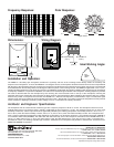
Polar Response:
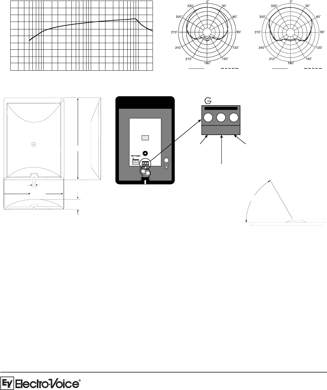
Dimensions:
!
#
# #
FREQUENCY IN HERTZ
RESPONSE IN dB
5 dB
5,000 Hz 10,000 Hz
500 Hz
1,000 Hz
5 dB per division
94.1 mm
(3.70 in.)
3.3 mm
(0.13 in.)
128.4 mm
(5.1 in.)
16 mm
(0.63 in.)
60°
ID EAL
WORKING
ANGLE
+
_
GROUND BRAID
(PIN 1)
RED WIRE
(PIN 2)
WHITE WIRE
(PIN 3)
+
_
Wiring Diagram:
Ideal Working Angle:
The RE90B is a boundary style microphone; therefore the symmetry and area of the mounting surface directly affects the sensitivity and
response of the microphones. To mount the RE90B on a rectangular surface, the microphone should be centered on the surface and positioned
with the front of the microphone facing the sound source along the longer dimension of the mounting surface. Ideally, the sources of sound should
be situated between the mounting surface and 60 degrees above the plane of the mounting surface. The RE90B is supplied with a 3.0-m (10 ft.)
miniature shielded cable with a male XLR-type connector. The RE90B is provided with the miniature shielded cable connected to the microphone
for temporary installation. For permanent installation, the cable can be routed through the bottom of the microphone. A drilling template is provided.
The cable is disconnected from the microphone by first removing the cross-recessed screw on the top of the microphone, removing the
protective grille screen and pop filter, then loosening the three screws on the terminal block. When reattaching the miniature cable, the contacts’
functions are printed on the printed circuit board. The RE90B has a balanced low-impedance, transformerless output. The balanced signal
appears across Pins 2 and 3 while the ground (shield) connection is Pin 1 (DIN 45 594). The output is phased so that positive acoustic pressure
on the transducer’s diaphragm produces a positive voltage on Pin 2 in accordance the industry convention.
Installation and Operation:
The microphone shall be a back-electret condenser type with a frequency response of 80 Hz to 15 kHz. The microphone shall have a half-
cardioid pattern with a rear response which is typically 15 dB below the front response at 1.0 kHz. The microphone shall have an open circuit
sensitivity of 25mV/Pa, and the output shall not be appreciably affected by the following temperature and humidity extremes: -29° to 74° C (-
20° to 165° F) when the relative humidity is 0-50%; -29° to 57° C (-20° to 135° F) when the relative humidity is 0-95%. The microphone shall
have a nominal, balanced transformerless output impedance of 200 Ohms. The microphone shall have a non-reflective black finish (RE90B) or
a non-reflective white finish (RE90BW). The cable color shall match the body color of the microphone. Dimensions of the RE90B shall be 94.1
mm (3.7 in.) wide, 128.4 mm (5.1 in.) long, and 16 mm (0.63 in.) high; the cable shall be 3.0 m (10 ft) long, 2.6 mm (0.106 in.) in diameter and
terminated in a black, non-reflecting male XLR-type connector. Termination to the microphone body shall be a terminal block. The Electro-Voice
RE90B and RE90BW are specified.
Architects’ and Engineers’ Specifications: